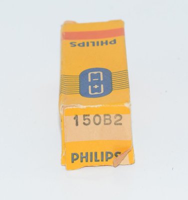
Introduction and History
The Philips 150B2 is a cold-cathode gas-discharge voltage stabiliser (voltage regulator) tube designed to maintain a stable 150-volt reference in electronic circuits. Manufactured by Philips (and its subsidiary brands including Valvo and Mullard), the 150B2 was introduced in the early 1950s, with Philips datasheet revisions documented from as early as December 1952 through June 1958. The tube was produced during the golden era of European valve manufacturing and found widespread use in laboratory instruments, communications equipment, military electronics, and high-fidelity audio power supplies where a precise, stable high-voltage reference was essential.
As a cold-cathode device, the 150B2 requires no heater filament — it operates via a controlled gas discharge (glow discharge) between its anode and cathode electrodes. This makes it inherently simple, reliable, and long-lived compared to heated-cathode regulators. The tube belongs to the Philips "B" series of voltage stabilisers, where the number preceding the "B" indicates the approximate stabilised voltage — in this case, 150 volts.
The 150B2 was manufactured by Philips in the Netherlands, by Valvo in Germany, and under various other Philips-affiliated brand names across Europe. It served both civilian and military markets, with the military designation CV2225 assigned under the British Common Valve (CV) numbering system.
Technical Specifications and Design
Tube Type and Construction
| Type Designation | 150B2 |
| Function | Voltage Stabiliser (Cold-Cathode Gas-Discharge Regulator) |
| Manufacturer | Philips / Valvo / Mullard |
| Base Type | Miniature 7-pin (B7G / Miniature 7p) |
| Envelope | Miniature glass envelope, max diameter 19 mm, max height 54 mm (overall max 54 mm including pins) |
| Heater | None (cold-cathode device) |
Pinout
The 150B2 uses a miniature 7-pin (B7G) base. Viewed from the bottom of the socket:
- Pin 1: Internal connection (i.c.) — do not connect
- Pin 2: Cathode (k)
- Pin 3: Internal connection (i.c.) — do not connect
- Pin 4: No connection
- Pin 5: Anode (a)
- Pin 6: Internal connection (i.c.) — do not connect
- Pin 7: Internal connection (i.c.) — do not connect
The key guide (k) on the base is located between pins 1 and 7. The anode (a) is on pin 5 and the cathode (k) is on pin 2. Note that several pins are marked as internal connections (i.c.) and must not be externally wired.
Typical Characteristics
| Parameter | Condition | Value |
|---|---|---|
| Average Operating Voltage (Va) | Nominal | 150 V |
| Va at Ia = 10 mA | Minimum | 146 V |
| Va at Ia = 10 mA | Maximum | 154 V |
| Ignition Voltage (Vign) | Max. at 50–500 lux illumination | 180 V |
| Ignition Voltage (Vign) | Max. in complete darkness | 225 V |
| Regulation (Voltage Variation) | Ia = 5–15 mA | 5 V max. |
| Variation of Va during 1000 hours | Ia = 10 mA | 1% max. |
| Temperature Coefficient of Va | — | 10 mV/°C |
Limiting Values (Absolute Maximum Ratings)
| Parameter | Value |
|---|---|
| Minimum Supply Voltage (Vb) | 180 V min. |
| Maximum Anode Current (Ia) | 15 mA |
| Minimum Anode Current (Ia) | 5 mA |
| Maximum Starting Current | 40 mA (for max. 40 seconds) |
| Maximum Ambient Temperature | 90 °C |
| Minimum Ambient Temperature | −55 °C |
Physical Dimensions
| Maximum Diameter | 19 mm |
| Maximum Seated Height | 47.6–48 mm (varies by revision) |
| Maximum Overall Height | 54 mm |
Important Notes from the Datasheet
- The tube must be operated only with the cathode negative and the anode positive.
- Equilibrium conditions are reached within 3 minutes of ignition.
- The tube should not be subjected to severe shock or continuous vibration.
- The minimum supply voltage of 180 V is necessary to ensure reliable starting (ignition) throughout the tube's life at an illumination of 50–500 lux. In complete darkness, the ignition voltage can be as high as 225 V.
- The starting current must not exceed 40 mA, and the duration of starting current must not exceed 40 seconds (Tav = max. 40 sec.).
Note: As a cold-cathode gas-discharge voltage stabiliser, the 150B2 does not have conventional amplification parameters such as amplification factor (μ), transconductance (gm), plate resistance (rp), or grid bias — these parameters are not applicable to this tube type.
Applications and Usage
The Philips 150B2 was designed primarily as a voltage reference and regulator element in power supply circuits. Its principal applications include:
Power Supply Regulation
The most common application for the 150B2 is as a shunt voltage regulator in DC power supplies. Connected in series with a ballast resistor across a higher-voltage DC source, the tube maintains a nearly constant 150 V across its terminals as the load current varies between 5 mA and 15 mA. The ballast resistor absorbs the difference between the unregulated supply voltage and the stabilised 150 V output, while the tube's current automatically adjusts to compensate for load variations.
Cascaded Voltage References
Multiple 150B2 tubes (or combinations with other voltage stabilisers such as the 85A2 or 108C1) can be connected in series to create higher regulated voltages. For example, two 150B2 tubes in series provide approximately 300 V regulated. This technique was widely used in professional and military equipment where precise, stable high-voltage supplies were required.
Bias Supply Regulation
In amplifier circuits, the 150B2 can serve as a stable bias voltage reference, providing a fixed 150 V reference from which precise grid bias voltages can be derived through resistive dividers.
Test and Measurement Equipment
The tube's excellent long-term stability (1% maximum drift over 1000 hours) and low temperature coefficient (10 mV/°C) made it suitable for use in laboratory instruments, oscilloscopes, and calibration equipment where voltage stability was critical.
Military and Industrial Applications
The wide operating temperature range of −55 °C to +90 °C and the assignment of the military designation CV2225 confirm that the 150B2 was specified for use in military and harsh-environment applications. Its cold-cathode design — requiring no heater warm-up time and consuming no heater power — was advantageous in battery-powered field equipment and in applications where instant-on capability was needed.
Typical Circuit Configuration
In a basic shunt regulator circuit, the 150B2 is connected with its anode to the positive rail through a series ballast resistor, and its cathode to the output ground reference (or to the next stabiliser tube in a cascade). The ballast resistor value is calculated to ensure the tube current remains within the 5–15 mA operating range under all expected load and supply voltage variations. The supply voltage must be at least 180 V to guarantee reliable ignition.
Sound Characteristics
As a voltage stabiliser tube, the 150B2 does not directly process audio signals and therefore does not have "sound characteristics" in the traditional sense that an amplifying valve (such as a 12AX7 or EL34) would. However, its influence on audio quality is indirect but significant:
Power Supply Noise and Regulation
Gas-discharge voltage stabilisers like the 150B2 are known to generate low-level electrical noise due to the inherent nature of the gas discharge process. This noise manifests as a broadband "hiss" or random fluctuation superimposed on the regulated voltage. In audio applications, this noise can potentially couple into sensitive signal stages if the regulated supply feeds preamplifier circuits directly. For this reason, additional RC filtering is typically employed after the stabiliser tube in high-fidelity applications.
Impact on Tonal Quality
Audiophiles and engineers who use gas-discharge stabilisers in their amplifier power supplies often report that a well-regulated B+ supply contributes to:
- Tighter bass response: Stable supply voltages prevent power supply sag that can soften low-frequency transients.
- Improved clarity and detail: Reduced supply voltage ripple and variation translates to lower intermodulation distortion in the amplifying stages.
- Better stereo imaging: Consistent operating points in both channels (when fed from a common regulated supply) improve channel matching.
- Reduced hum: The stabiliser's ability to reject supply ripple reduces residual mains hum in the audio output.
However, some purist audiophiles prefer unregulated or choke-filtered supplies, arguing that gas-discharge regulators can introduce their own subtle noise signature. The choice between regulated and unregulated supplies remains a matter of design philosophy and personal preference in the audio community.
Microphonic Sensitivity
The Philips datasheet explicitly warns that the 150B2 should not be subjected to severe shock or continuous vibration. Gas-discharge tubes can be microphonic — physical vibration can modulate the gas discharge and create audible artifacts. In audio equipment, the 150B2 should be mounted with vibration isolation (rubber grommets or similar) and positioned away from loudspeakers and transformers that might transmit mechanical vibration.
Equivalent or Substitute Types
| Type | Manufacturer/Standard | Notes |
|---|---|---|
| CV2225 | British Military (CV Register) | Direct equivalent; identical specifications. Military-grade version of the 150B2. |
| 0B2 | American (RETMA/EIA) | American equivalent 150V gas-discharge stabiliser. Uses the same miniature 7-pin base. The 0B2 is the most commonly encountered equivalent in American equipment. Specifications are very similar (108V nominal for 0B2 — note: the 0B2 is actually a 108V stabiliser, NOT a direct 150V equivalent; see note below). |
Important Clarification on the 0B2: The American 0B2 is a 108-volt stabiliser, NOT a 150-volt type, and therefore is not a direct substitute for the 150B2 despite the similar naming convention. The American 150-volt cold-cathode stabiliser equivalent should be verified against specific cross-reference guides. The only confirmed direct and identical substitute for the 150B2 is the CV2225.
Other Philips-family 150V stabilisers that may be related include types produced by Mullard and other Philips subsidiaries under the same 150B2 designation. Valvo-branded 150B2 tubes are identical to Philips-branded examples, as Valvo was the German arm of the Philips tube manufacturing operation.
Note: If substituting tubes, always verify that the replacement has the same stabilising voltage, current range, ignition voltage, and pinout. Using a stabiliser with the wrong voltage rating will result in incorrect regulated output voltage and potential circuit damage.
Notable Characteristics
Cold-Cathode Operation
The 150B2 requires no heater supply, making it extremely efficient in terms of power consumption. The only power dissipated is the product of the stabilised voltage and the discharge current (approximately 150 V × 10 mA = 1.5 W at the nominal operating point). This is a significant advantage over heated-cathode voltage regulators.
Light Sensitivity
One of the most interesting characteristics of the 150B2 is its sensitivity to ambient light levels for ignition. The datasheet specifies two different maximum ignition voltages: 180 V at 50–500 lux illumination, and 225 V in complete darkness. This is because photons striking the cathode surface help initiate the gas discharge by providing seed electrons through the photoelectric effect. In practical circuit design, the supply voltage must be sufficient to guarantee ignition under the worst-case (darkest) conditions expected, or the tube must be exposed to ambient light. Some equipment designs included a small pilot lamp near the stabiliser tube to ensure reliable ignition.
Excellent Long-Term Stability
The 150B2 exhibits outstanding long-term voltage stability, with a maximum drift of only 1% over 1000 hours of continuous operation at 10 mA. This level of stability was exceptional for the era and made the tube suitable for precision instrumentation.
Low Temperature Coefficient
With a temperature coefficient of only 10 mV/°C, the 150B2 maintains excellent voltage stability across a wide temperature range. Over a 50°C temperature swing, the output voltage would change by only 0.5 V — a variation of approximately 0.33% of the nominal 150 V output.
Wide Operating Temperature Range
The specified ambient temperature range of −55 °C to +90 °C makes the 150B2 suitable for extreme environmental conditions, from arctic military installations to tropical equipment rooms.
Fast Settling Time
The tube reaches equilibrium conditions within 3 minutes of ignition, which is relatively fast for a precision voltage reference of this era.
Characteristic V-I Curve
The Philips datasheet includes characteristic curves showing the relationship between anode voltage (Va) and anode current (Ia). The curves show a nearly vertical characteristic in the 5–15 mA operating range, with the voltage varying only slightly (within the 146–154 V limits) as current changes. The dashed lines on the characteristic curves indicate the voltage limits (manufacturing tolerance bounds), demonstrating the tight production control Philips maintained on this tube type.
Visible Glow Discharge
When operating, the 150B2 exhibits a characteristic violet-blue glow discharge visible through the glass envelope. This glow is produced by the ionisation of the gas fill (typically a mixture of neon and other noble gases with specific additives to achieve the desired stabilising voltage). The glow should be uniform and stable; flickering or uneven glow patterns can indicate a worn or defective tube.
Usage in the Audio Community
Power Supply Regulation in Valve Amplifiers
The 150B2 has found a dedicated following among audio enthusiasts who build and restore valve (tube) amplifiers. Its primary role in audio applications is as a B+ voltage regulator in preamplifier and phono stage power supplies. Many classic European amplifier and tuner designs from the 1950s and 1960s incorporated the 150B2 (or its equivalents) to provide stable, well-regulated plate supply voltages for sensitive front-end stages.
Phono Preamplifier Power Supplies
Phono preamplifiers are particularly sensitive to power supply noise and voltage variations because they operate at very high gain (typically 40–60 dB). The 150B2's ability to provide a stable 150 V reference with good ripple rejection makes it an attractive choice for regulating the B+ supply in phono stages. Builders of high-end phono preamps sometimes use cascaded gas-discharge stabilisers (e.g., a 150B2 followed by an 85A2) to create a multi-stage regulated supply with extremely low noise.
DIY and Boutique Amplifier Projects
The DIY audio community values the 150B2 for several reasons:
- Simplicity: A shunt regulator using a 150B2 requires only the tube and a single ballast resistor — no complex feedback circuits or semiconductor components.
- Aesthetic appeal: The visible violet-blue glow discharge adds visual drama to open-chassis or exposed-tube amplifier builds.
- Period authenticity: Restorers of vintage European equipment seek NOS (New Old Stock) 150B2 tubes to maintain originality in classic Philips, Telefunken, and other European designs.
- Perceived sonic benefits: Some audiophiles believe that gas-discharge regulated supplies sound "more natural" or "more open" than semiconductor-regulated alternatives, though this remains a subjective and debated topic.
Availability and Collectibility
The 150B2 is no longer in production, but NOS (New Old Stock) examples from Philips, Valvo, Mullard, and other manufacturers remain available through specialist valve dealers and online marketplaces. Valvo-branded NOS examples are particularly sought after. Prices for NOS 150B2 tubes are generally moderate compared to popular audio amplifying valves, as demand is limited primarily to restoration and specialist power supply applications. However, tested and guaranteed examples command a premium.
Practical Considerations for Audio Use
Audio builders using the 150B2 should observe the following practical guidelines:
- Noise filtering: Always follow the stabiliser with an RC filter (typically 1–10 kΩ resistor and 10–100 µF capacitor) to attenuate the gas-discharge noise before feeding sensitive audio stages.
- Vibration isolation: Mount the tube using rubber grommets or a vibration-dampening socket to minimise microphonic effects.
- Adequate supply voltage: Ensure the raw B+ supply is at least 180 V (preferably higher, to account for the ballast resistor drop) to guarantee reliable ignition under all conditions.
- Current budget: The total current drawn through the stabiliser circuit (tube current plus load current reflected through the ballast resistor) must keep the tube within its 5–15 mA operating range under all signal conditions.
- Warm-up time: Allow at least 3 minutes for the tube to reach equilibrium before expecting full performance from the regulated supply.
- Replacement testing: When replacing a 150B2, test the new tube's actual stabilising voltage, as individual tubes can vary between 146 V and 154 V. In critical applications, select tubes for closely matched voltage.
Notable Equipment Using the 150B2
The 150B2 appeared in numerous European-designed instruments and audio equipment from the 1950s and 1960s, including Philips laboratory instruments, professional broadcast equipment, and high-end consumer electronics. Specific equipment models should be confirmed against service manuals and schematic archives, but the tube was a standard component in many Philips and Philips-affiliated designs of the era.