Introduction and History
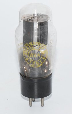
The Philips 1561 is a full-wave (Vollweg/Biplaque) high vacuum rectifier tube manufactured by Philips, dating from the early 1930s. The datasheet carries a date of 14/6/33 (June 14, 1933), placing this tube firmly in the golden era of European valve development. Produced under the Philips and Miniwatt BVA brands, the 1561 was designed to provide reliable DC power supply rectification for radio receivers and amplifiers of the period.
As a directly-heated, high-vacuum diode rectifier, the 1561 was engineered for full-wave rectification using a center-tapped power transformer. Its high-vacuum construction (Hochvakuum) distinguishes it from mercury-vapor rectifiers of the same era, offering more predictable behavior and freedom from the temperature-dependent characteristics of mercury types. The tube was manufactured during a period when Philips was establishing itself as one of Europe's premier valve manufacturers, and the 1561 reflects the robust engineering standards of that era.
The 1561 appears to have been produced in at least two variants or revisions: an earlier version rated for 2×500 V AC anode voltage with 120 mA maximum rectified current, and a later, more commonly documented version rated for 2×300 V AC anode voltage with 160 mA maximum rectified current. Both variants share the same physical dimensions, filament ratings, and base type. This article covers both variants as documented in the manufacturer's datasheet.
Technical Specifications and Design
Electrical Ratings
| Parameter | Symbol | Variant 1 (High Voltage) | Variant 2 (Standard) |
|---|---|---|---|
| Filament Voltage | Vf | 4.0 V | 4.0 V |
| Filament Current | If | approx. 2.0 A | approx. 2.0 A |
| Max. AC Anode Voltage | Va max | 2 × 500 V | 2 × 300 V |
| Max. Rectified Current | Ia max | 120 mA | 160 mA |
Note: The filament current is specified as "ca." (circa/approximately) 2.0 A in the datasheet, indicating a nominal value with some tolerance. The filament is directly heated at 4.0 V, which was a common European standard of the era.
As a rectifier diode, the 1561 does not have amplification factor (μ), transconductance (gm), plate resistance (rp), or grid bias specifications — these parameters apply only to amplifying tubes (triodes, pentodes, etc.). The 1561 has no control grid; it is a pure diode with two anodes and a common cathode/filament.
Regulation Characteristics
The Philips datasheet includes a voltage regulation curve plotting DC output voltage (Va) versus rectified current (Ia) at three AC input voltage levels:
- Veff = 2 × 500 V: Output drops from approximately 700 V at no load to approximately 500 V at 120 mA
- Veff = 2 × 400 V: Output drops from approximately 560 V at no load to approximately 400 V at 120 mA
- Veff = 2 × 300 V: Output drops from approximately 400 V at no load to approximately 280 V at 120 mA
These curves reveal a moderate internal resistance, typical of directly-heated high-vacuum rectifiers of this era. The voltage drop under load is gradual and predictable, which is a desirable characteristic for power supply design.
Physical Specifications
| Parameter | Value |
|---|---|
| Overall Length | 125 mm |
| Maximum Diameter | 58 mm |
| Base Type | A 35 |
| Base Connection | S III |
| Envelope | Glass, ST-type bulb (typical for era) |
| Construction | High Vacuum (Hochvakuum) |
The A 35 base is a European-style base common to Philips tubes of the early 1930s. The S III base connection scheme defines the pin arrangement for the two anodes and the filament connections. Builders working with this tube should consult original Philips base diagrams for the S III pinout, as this is a vintage European base type not commonly encountered in later equipment.
Applications and Usage
The Philips 1561 was designed primarily as a power supply rectifier for radio receivers and audio amplifiers of the 1930s. Its principal applications include:
- Full-wave rectification: Used with a center-tapped power transformer to provide full-wave DC rectification, the standard topology for high-quality power supplies of the era.
- Radio receiver power supplies: Providing B+ voltage for multi-tube radio receivers, where the 2×300 V or 2×500 V AC input ratings covered the range of typical transformer secondary voltages.
- Amplifier power supplies: Supplying DC plate voltage for audio amplifier circuits, where the 120–160 mA current capability was sufficient for most domestic amplifier designs.
- General-purpose rectification: Any application requiring a reliable, high-vacuum full-wave rectifier with moderate current capability.
The high-vacuum construction makes the 1561 suitable for applications where immediate operation is desired without the warm-up delay associated with mercury-vapor rectifiers. It also avoids the RF noise that mercury-vapor types can generate, making it preferable in sensitive radio receiver applications.
Sound Characteristics
While rectifier tubes do not directly amplify audio signals, experienced audiophiles and amplifier designers recognize that the rectifier tube has a meaningful influence on the overall sonic character of a tube amplifier. The 1561, as a directly-heated high-vacuum rectifier, exhibits characteristics that are valued in certain audio applications:
- Soft, gradual power delivery: Like other directly-heated rectifiers, the 1561 provides a "soft start" as the filament heats up, gradually bringing the B+ voltage to its operating level. This is gentler on filter capacitors and other tubes in the circuit.
- Moderate internal resistance: The regulation curves show a noticeable voltage drop under load, which translates to a degree of "sag" in the power supply. In guitar amplifiers and certain hi-fi designs, this sag is perceived as a slight compression and warmth in the sound, particularly during dynamic peaks.
- Smooth, organic tonality: Directly-heated rectifiers like the 1561 are generally described as contributing to a smoother, more organic sound compared to solid-state rectification. The slight softening of transients due to the rectifier's internal impedance is often perceived as musical and natural.
- Vintage character: The 1561's 1930s-era construction and materials contribute to what listeners describe as a distinctly vintage tonal character — warm, slightly rounded, with a gentle presentation that avoids harshness.
It should be noted that the sonic influence of any rectifier tube is secondary to the amplifying tubes and circuit topology. However, in carefully designed amplifiers, swapping rectifier types can produce audible differences, and vintage European rectifiers like the 1561 are often prized for their contribution to a refined, musical sound.
Equivalent or Substitute Types
The following tubes are documented as close or identical substitutes for the Philips 1561:
| Type | Relationship | Notes |
|---|---|---|
| CV1039 | Close/identical substitute | British military (CV) designation. Should be directly interchangeable. |
| CV1289 | Close/identical substitute | British military (CV) designation. Should be directly interchangeable. |
The CV (Common Valve) designations were assigned by the British military services to standardize valve types across manufacturers. The existence of two CV numbers (CV1039 and CV1289) may reflect the two variants of the 1561 (the 2×500 V/120 mA version and the 2×300 V/160 mA version), or may represent different assessment periods. Users should verify the specific ratings of any CV-designated substitute against their application requirements.
Important: Due to the vintage A 35 base type and S III connection scheme, the 1561 is not directly interchangeable with more common later rectifiers such as the 5U4, 5Y3, GZ34, or similar types without socket adaptation and careful verification of electrical ratings. The 4.0 V directly-heated filament is specific to this family of European tubes.
Notable Characteristics
- Multiple variants: The datasheet documents at least two versions — a higher-voltage variant (2×500 V, 120 mA) and a standard variant (2×300 V, 160 mA). Both share the same physical envelope and filament ratings, suggesting internal construction differences in the anode spacing or filament emission capability.
- Directly-heated cathode: The 4.0 V, 2.0 A filament serves as both heater and cathode, a design that provides fast warm-up and is characteristic of rectifier tubes of this era.
- Robust construction: The 58 mm diameter glass envelope and 125 mm overall length indicate a substantial tube with generous internal spacing, contributing to reliability and long service life.
- Excellent regulation curves: The published Philips regulation data shows smooth, predictable voltage-versus-current characteristics across the operating range, facilitating accurate power supply design.
- High-vacuum design: Unlike mercury-vapor rectifiers, the 1561 operates reliably across a wide temperature range and does not require a warm-up period before applying plate voltage (though allowing filament warm-up is still good practice).
- Early 1930s vintage: With a datasheet date of June 1933, the 1561 represents early Philips engineering and is a collectible item for vintage radio enthusiasts.
Usage in the Audio Community
The Philips 1561 occupies a niche position in the audio community, valued primarily by vintage radio restorers and collectors of early European audio equipment. Its usage and reputation can be characterized as follows:
- Vintage radio restoration: The primary demand for the 1561 comes from restorers of 1930s European radio receivers that originally specified this tube. Authentic restoration of Philips and other European radios from this era often requires sourcing original or NOS (New Old Stock) 1561 tubes.
- Collector interest: As an early 1930s Philips product, the 1561 is sought by tube collectors, particularly those specializing in pre-war European valves. Tubes tested on AVO valve testers (as noted in the reference data for Philips Miniwatt BVA examples) command particular interest as their condition can be verified.
- Custom amplifier builds: A small number of adventurous DIY audio builders incorporate vintage European rectifiers like the 1561 into custom power supply designs, appreciating both the aesthetic appeal of the large glass envelope and the sonic characteristics of directly-heated rectification. The A 35 base requires sourcing vintage sockets, adding to the challenge and exclusivity of such builds.
- Power supply character: Audio enthusiasts who have used the 1561 in amplifier power supplies report that it contributes a characteristically warm, slightly soft power delivery that complements vintage-voiced amplifier circuits. The moderate voltage regulation (visible in the published curves) provides a degree of natural compression that many find musically pleasing.
- Availability: The 1561 is uncommon on the modern market. When found, it typically appears as NOS stock from European sources or as pulls from vintage equipment. Prices vary considerably based on condition, testing results, and brand markings (Philips Miniwatt BVA examples being particularly desirable).
For audio builders considering the 1561, it is essential to source appropriate A 35 base sockets and to design the power transformer secondary to match the tube's ratings. The 4.0 V filament winding must be capable of supplying approximately 2.0 A, and the high-voltage secondary should not exceed 2×500 V RMS (for the high-voltage variant) or 2×300 V RMS (for the standard variant). Adequate filter capacitance and bleeder resistors should be employed to ensure proper operation within the tube's maximum rectified current ratings of 120 mA or 160 mA respectively.