1. Introduction and History
The Philips 16A5 is a beam-power pentode designed as a combined frame (vertical) time base and sound output tube for television receivers. It was introduced by N.V. Philips' Gloeilampenfabrieken of Eindhoven, Holland, with its datasheet dated 6 June 1951 and released through RTMA release #1029 on 16 October 1951. The tube was manufactured by Philips and its associated brands, including Mullard in England and Philips Miniwatt in Holland.
The 16A5 belongs to the 16-volt heater series of tubes developed primarily for series-string heater operation in AC/DC television receivers common in the European market during the early 1950s. Its 16.5-volt, 300 mA heater was designed to be wired in series with other tubes in the receiver, eliminating the need for a heater transformer. This was a cost-effective approach widely adopted in post-war consumer electronics.
As a dual-purpose valve, the 16A5 was engineered to serve both as a vertical deflection output tube — generating the sawtooth waveform needed to drive the frame scanning coils of a CRT — and as an audio output stage capable of delivering several watts of sound power. This versatility made it an economical choice for television manufacturers seeking to minimize tube count and chassis complexity.
2. Technical Specifications and Design
Physical Specifications
| Cathode | Coated unipotential |
| Base | Small button noval 9-pin (B9A) |
| JETEC Basing Designation | 9BL |
| Bulb | T6½ |
| Maximum Overall Length | 3 1/16" |
| Maximum Seated Height | 2 13/16" |
| Bulb Length Excluding Tip | 2 7/16" ± 3/32" |
| Maximum Diameter | 7/8" |
| Mounting Position | Any |
Pin Connections (Bottom View)
| Pin 1 | Not connected |
| Pin 2 | Grid No. 1 (Control Grid) |
| Pin 3 | Cathode and Grid No. 3 (Suppressor Grid) |
| Pin 4 | Heater |
| Pin 5 | Heater |
| Pin 6 | Internally connected |
| Pin 7 | Plate (Anode) |
| Pin 8 | Internally connected |
| Pin 9 | Grid No. 2 (Screen Grid) |
Note: Pins 1, 6, and 8 are internal connections and should not be used for external wiring.
General Electrical Data
| Heater Voltage | 16.5 volts |
| Heater Current | 300 mA |
Direct Interelectrode Capacitances
| Grid No. 1 to all other elements except plate | 11 μμF |
| Plate to all other elements except Grid No. 1 | 5.9 μμF |
| Plate to Grid No. 1 | max. 1 μμF |
| Grid No. 1 to heater | max. 0.15 μμF |
Maximum Ratings
| Plate Voltage (without current) | 550 volts |
| Peak Positive Plate Voltage | 2500 volts1 |
| Peak Negative Plate Voltage | 500 volts |
| Average Plate Voltage | 250 volts |
| Plate Dissipation | 9 watts |
| Grid No. 2 Voltage (without current) | 550 volts |
| Grid No. 2 Voltage | 250 volts |
| Grid No. 2 Dissipation | 2.5 watts |
| Cathode Current | 75 mA |
| Grid Current Starting Point (Grid No. 1 current = +0.3 μA) | −1.3 volts |
| Grid No. 1 Circuit Resistance (automatic bias) | 1 megohm |
| Grid No. 1 Circuit Resistance (fixed bias) | 0.4 megohm |
| Heater-Cathode Voltage | 200 volts |
| External Heater-Cathode Resistance | 20,000 ohms |
1 Maximum permitted pulse duration 10% of one cycle, with a maximum of 2 milliseconds.
Operating Conditions as Class A Sound Output Amplifier (Single-Ended)
| Parameter | Condition 1 | Condition 2 |
|---|---|---|
| Plate and Supply Voltage | 170 V | 200 volts |
| Grid No. 2 Series Resistor | 0 | 680 ohms |
| Grid No. 1 Bias | −10.4 V | −13.9 volts |
| Plate Current | 53 mA | 45 mA |
| Grid No. 2 Current | 10 mA | 8.5 mA |
| Transconductance | 9000 μmhos | 7600 micromhos |
| Plate Resistance | 20,000 Ω | 24,000 ohms |
| Amplification Factor (Grid No. 2 w.r.t. Grid No. 1) | 10 | 10 |
| Load Resistance | 3000 Ω | 4000 ohms |
| Output at 10% Distortion | 4.0 W | 4.2 watts |
| A.C. Grid No. 1 Voltage at 10% Distortion | 6.0 V rms | 7.0 volts (rms) |
| A.C. Grid Voltage at 50 mW Output | 0.5 V rms | 0.55 volts (rms) |
Operating Conditions as Class A Sound Output Amplifier (Push-Pull, Two Tubes)
| Parameter | Condition 1 | Condition 2 |
|---|---|---|
| Plate Voltage | 170 V | 200 volts |
| Grid No. 2 Voltage | 170 V | 200 volts |
| Cathode Resistor | 100 Ω | 135 ohms |
| Load Resistance (plate to plate) | 4000 Ω | 4000 ohms |
| A.C. Grid No. 1 Voltage | 0 / 2×9.3 V rms | 0 / 2×13.5 volts (rms) |
| Plate Current | 2×46 / 2×50 mA | 2×45 / 2×52 mA |
| Grid No. 2 Current | 2×8.7 / 2×17 mA | 2×8.5 / 2×19 mA |
| Output | 0 / 9 W | 0 / 12 watts |
| Distortion | — / 5% | — / 5% |
Optimum Peak Plate Current in Frame Output Operation
To allow for tube spread and deterioration during life in frame output application, the circuit should be designed around a peak plate current not exceeding 90 mA at a plate voltage of 50 volts and a Grid No. 2 voltage of 170 volts, and not exceeding 120 mA at a plate voltage of 60 volts and a Grid No. 2 voltage of 200 volts.
3. Applications and Usage
The Philips 16A5 was designed as a dual-purpose tube for television receivers, fulfilling two distinct roles:
Frame (Vertical) Time Base Output
The primary application of the 16A5 was as a vertical deflection output tube in television sets. In this role, the tube amplified the sawtooth waveform generated by the frame oscillator and drove the vertical deflection coils of the cathode ray tube. The tube's ability to handle high peak positive plate voltages (up to 2500 V in pulses of 10% duty cycle, maximum 2 ms) and its robust cathode current capability (75 mA maximum) made it well-suited for this demanding application. The datasheet specifically recommends designing circuits around peak plate currents of 90 mA (at 50 V plate, 170 V screen) or 120 mA (at 60 V plate, 200 V screen) to account for tube-to-tube variation and aging.
Sound Output Amplifier
The 16A5 was equally capable as an audio output stage. In single-ended Class A operation at 170 V plate supply, it could deliver 4.0 watts at 10% distortion into a 3000-ohm load, requiring only 6.0 V rms of grid drive. At the higher 200 V supply condition with a 680-ohm screen series resistor and 4000-ohm load, output increased to 4.2 watts at 10% distortion.
In push-pull Class AB configuration (without grid No. 1 current), a pair of 16A5 tubes could deliver 9 watts at 170 V or 12 watts at 200 V plate supply, both at 5% distortion into a 4000-ohm plate-to-plate load. These power levels were more than adequate for the sound requirements of 1950s television receivers.
Series-String Heater Operation
With its 16.5 V, 300 mA heater, the 16A5 was designed for series-string heater chains in transformerless AC/DC television receivers. This was a common design approach in European sets of the era, where the heaters of all tubes in the receiver were connected in series across the mains supply, with a dropping resistor to absorb the excess voltage. The 300 mA heater current was a standard value shared by many tubes in the Philips/Mullard television tube lineup.
4. Sound Characteristics
The Philips 16A5, while primarily a television tube, possesses sonic characteristics that are noteworthy for those who have encountered it in audio applications:
Tonal Character: The 16A5 exhibits the warm, full-bodied midrange typical of European beam pentodes from the early 1950s. With a transconductance of 9000 μmhos (at 170 V) and a relatively low plate resistance of 20,000 ohms, the tube has a lively, responsive character that translates well to audio reproduction. The high transconductance for its class means it is sensitive to input signals, requiring only modest drive levels to reach full output.
Bass Response: In single-ended operation with the recommended 3000–4000 ohm load impedance, the 16A5 produces a solid, well-defined bass that is characteristic of beam-power tubes. The relatively high quiescent current (45–53 mA) ensures good core magnetization in single-ended output transformers, contributing to bass authority.
Treble and Detail: The interelectrode capacitances — particularly the 11 pF input capacitance and 5.9 pF output capacitance — are moderate for a power pentode, and the plate-to-grid capacitance is held to a maximum of 1 pF. This results in reasonable high-frequency extension, though the tube was not designed for wide-bandwidth hi-fi applications. In triode-strapped mode (screen tied to plate), the tube would exhibit a warmer, more rolled-off top end with significantly reduced output power but lower distortion.
Distortion Profile: As with most beam pentodes, the 16A5 produces predominantly second and third harmonic distortion in single-ended operation. The datasheet performance curves show that distortion rises progressively with output power, reaching 10% at the rated maximum output. At lower power levels — say 50 milliwatts, requiring only 0.5 V rms of drive — distortion is very low, suggesting the tube would perform well in applications where it is not driven to its limits. In push-pull, the cancellation of even-order harmonics brings distortion down to 5% at full rated output (9–12 watts), which is respectable for the era.
Dynamic Character: The 16A5's dual role as a deflection tube means it was designed to handle rapidly changing current demands — a characteristic that translates to good transient response in audio applications. The tube can swing large plate currents quickly, which benefits musical dynamics and punch.
5. Equivalent or Substitute Types
The Philips 16A5 is a relatively specialized tube, and direct equivalents are limited:
- Mullard 16A5: Identical tube manufactured by Mullard (the British arm of the Philips group). Fully interchangeable in all respects.
- Philips Miniwatt 16A5: Same tube under the Philips Miniwatt brand, manufactured in Holland. Fully interchangeable.
The 16A5 does not have a widely recognized direct equivalent in the American (RETMA/EIA) numbering system. Its unusual 16.5-volt heater voltage places it in a specific series-string family that was predominantly a European design approach. Tubes with similar electrical characteristics but different heater voltages (such as the 6AQ5/EL90 family for 6.3 V heater applications) are not direct substitutes due to the heater voltage difference and differing pinout arrangements.
Note: Any substitution should be carefully verified against the original equipment manufacturer's schematic, as the 16A5's heater voltage, pinout, and operating conditions are specific to its intended series-string television applications. The internally connected pins (6 and 8) must also be accounted for in any substitution attempt.
6. Notable Characteristics
- Dual-Purpose Design: The 16A5 is one of relatively few tubes explicitly designed and rated for both frame deflection and audio output service. This versatility was a significant advantage for television manufacturers seeking to reduce parts count and simplify inventory.
- High Peak Plate Voltage Rating: The 2500-volt peak positive plate voltage rating (under pulsed conditions) is remarkably high for a tube of this size and reflects its deflection output heritage. This rating allows the tube to handle the large inductive flyback pulses generated during vertical retrace.
- Robust Cathode: The coated unipotential cathode is designed for the demanding conditions of deflection service, where cathode current varies dramatically over each scanning cycle. The 75 mA maximum cathode current rating provides adequate headroom for both deflection and audio applications.
- Series-String Heater: The 16.5 V, 300 mA heater is specifically designed for series-string operation, a hallmark of transformerless European television design. This makes the tube less versatile for general-purpose use but perfectly suited to its intended application.
- High Transconductance: At 9000 μmhos (170 V condition), the 16A5 offers high sensitivity, requiring relatively little drive voltage to produce full output. This reduced the demands on the preceding driver stage.
- Screen Grid Amplification Factor: The amplification factor of Grid No. 2 with respect to Grid No. 1 is 10, which is a useful parameter for circuit design, particularly when the screen grid voltage varies with signal (as in some deflection circuits).
- Comprehensive Characteristic Curves: The original Philips datasheet provides an unusually thorough set of characteristic curves, including plate current vs. grid bias at multiple screen voltages (100 V, 170 V, and 200 V), plate characteristics, screen current characteristics, and detailed performance curves for both single-ended and push-pull operation showing output power, distortion, and currents as functions of drive voltage.
- Any Mounting Position: The tube may be mounted in any position, providing flexibility in chassis layout — an important consideration in the often cramped interiors of television receivers.
7. Usage in the Audio Community
The Philips 16A5 occupies a niche position in the audio community. It was never a mainstream audio tube in the way that the EL84, EL34, or 6L6 became household names among audiophiles. However, it has attracted interest from several quarters:
Vintage Television Restoration
The primary demand for the 16A5 comes from restorers of vintage 1950s European television sets, where the tube serves its original dual purpose. In this context, the audio performance of the 16A5 is experienced as part of the complete television receiver, and restorers often comment on the surprisingly good sound quality of these early TV sets when properly restored with fresh components.
DIY and Experimental Audio
The 16A5 has found a small following among DIY tube audio enthusiasts who enjoy experimenting with obscure and unusual tube types. Its appeal lies in several factors:
- Availability and Price: As a television tube that was produced in large quantities but is no longer in mainstream demand, NOS (New Old Stock) examples from Philips, Mullard, and Philips Miniwatt can sometimes be found at reasonable prices compared to more sought-after audio tubes.
- Adequate Power: The 4+ watts available in single-ended Class A, or 9–12 watts in push-pull, is sufficient for driving efficient loudspeakers in a domestic listening environment.
- High Sensitivity: The high transconductance means the tube can be driven directly by a single voltage amplifier stage, simplifying amplifier design.
- Build Quality: Philips and Mullard tubes from this era are renowned for their construction quality, with robust internal structures and reliable long-term performance.
Practical Considerations for Audio Use
Builders considering the 16A5 for audio projects should be aware of several practical issues:
- Heater Supply: The 16.5 V, 300 mA heater is non-standard for most audio applications. A dedicated heater supply or a carefully designed series-string arrangement is required. This is perhaps the single biggest obstacle to casual audio use of this tube.
- Output Transformer Matching: The recommended load impedances of 3000–4000 ohms are within the range of commonly available single-ended and push-pull output transformers, making this aspect of circuit design straightforward.
- Bias Requirements: The tube operates with modest negative grid bias (−10.4 V at 170 V supply, −13.9 V at 200 V supply), which can be easily provided by cathode bias resistors. The datasheet permits grid circuit resistances up to 1 megohm with automatic bias, simplifying the driver stage coupling.
- Heater-Cathode Voltage: The 200 V maximum heater-cathode voltage rating provides adequate margin for most audio circuit topologies, but designers should verify this in circuits with elevated cathode voltages.
Collectibility
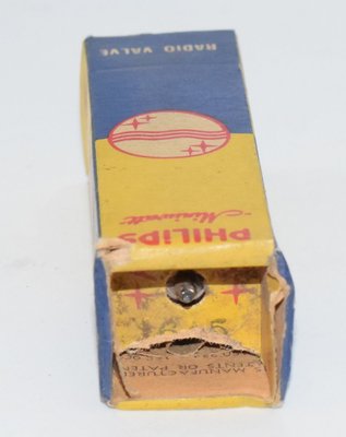
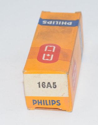
Among tube collectors, the 16A5 is valued primarily as a representative of the Philips/Mullard television tube range of the early 1950s. NOS examples in original packaging from Philips Great Britain, Mullard England, and Philips Miniwatt Holland are available from specialist dealers. While not commanding the premium prices of famous audio tubes, well-preserved examples are appreciated by collectors of European valve heritage.
The 16A5 serves as a reminder of an era when tube designers created remarkably versatile components that could serve multiple functions within a single piece of equipment — a design philosophy driven by economic necessity that nonetheless produced tubes of genuine engineering elegance.