1. Introduction and History
The 1BQ2 is a high-vacuum, single-anode rectifier tube designed specifically for generating Extra High Tension (EHT) voltages in television receivers. Manufactured by Amperex (a Philips subsidiary) and other major valve producers, the 1BQ2 was developed during the 1960s to serve as the EHT rectifier in the line (horizontal) time base section of CRT television sets. Its European designation is the DY802, and it belongs to the broader family of EHT "booster" diodes that were essential components in virtually every cathode ray tube television of the era.
The 1BQ2 features a chemically treated envelope designed to prevent flash-over under conditions of high humidity and low atmospheric pressure — a critical requirement given that the tube operates at voltages up to 25,000 volts peak inverse. This chemical treatment of the glass was a notable engineering advancement that improved reliability in tropical and high-altitude environments where corona discharge and arcing were persistent problems in earlier EHT rectifier designs.
The Amperex datasheet for this tube is dated April 1967 (4/67), placing its production firmly in the golden age of vacuum tube television technology, just as solid-state replacements were beginning to appear on the horizon. Despite the transition to semiconductor-based EHT systems, the 1BQ2/DY802 remained in production and service for many years due to the enormous installed base of CRT televisions worldwide.
2. Technical Specifications and Design
Mechanical Characteristics
| Bulb | T 6-1/2, glass |
| Base | E9-1, noval (9-pin miniature) |
| Cap | C1-2 (top cap for plate connection) |
| Mounting Position | Any |
| Dimensions | See outline drawing; max diameter 7/8 inch; seated height approximately 2-21/32 inch max, overall 2-29/32 inch max |
Pin Connections (E9-1 Noval Base)
| Pin | Connection |
|---|---|
| 1 | Heater, Cathode, Screen |
| 2 | Heater |
| 3 | Internal Connection (must never be grounded) |
| 4 | Heater, Cathode, Screen |
| 5 | Heater |
| 6 | Heater, Cathode, Screen |
| 7 | Internal Connection (must never be grounded) |
| 8 | Heater |
| 9 | Heater, Cathode, Screen |
| P (Top Cap) | Plate (Anode) |
Important Notes on Pin Connections:
- Pins 1, 4, 6, and 9 can be used for fixing an anti-corona ring.
- Circuit elements having the same potential as the heater (e.g., a series resistor) may be connected to pins 3 and 7. These pins must never be grounded.
- If the tube operates at high inverse plate voltages and/or under conditions of high relative humidity or low pressure, the metal cap should receive an insulating cover to avoid corona phenomena.
Heater Characteristics
| Heater Arrangement | Parallel supply |
| Heater Voltage (AC or DC) | 1.4 volts ±10% |
| Heater Current | 0.6 amps |
Note: For use as an EHT rectifier in television receivers, the heater voltage should be adjusted to its nominal value at a DC output current of 200 μA. At an increase of the DC output current to 400–800 μA (which may occur during operation), the decrease of the heater voltage may amount to 15% maximum. These requirements hold for nominal voltage and full horizontal scanning of the picture tube.
Electrical Characteristics
| Direct Interelectrode Capacitance (Plate to All) | 1.0 pF |
Operating Characteristics
| Output Current (Io) | 200 μA |
| Output Voltage (Vo) | 20 KV |
Maximum Ratings (Design Center Values)
| Plate Inverse Voltage (DC component) | 20,000 volts |
| Peak Plate Inverse Voltage | 25,000 volts (absolute maximum 30,000 volts) |
| Average Output Current | 500 μA |
| Peak Output Current | 50 mA |
| Filter Input Capacitance | 3,000 pF |
Additional Notes on Maximum Ratings:
- The peak plate inverse voltage rating of 25,000 volts applies with a maximum pulse duration of 22% of a cycle, but max 18 microseconds.
- During short periods as in TV operation, the average output current (Ib) may reach a maximum of 800 μA.
Note: As the 1BQ2 is a rectifier diode, specifications such as amplification factor (μ), transconductance (gm), plate resistance (rp), plate dissipation, and grid bias range are not applicable to this tube type. It has no control grid — it is a simple diode structure optimized for high-voltage rectification.
3. Applications and Usage
The 1BQ2 was designed for a single, highly specialized purpose: EHT (Extra High Tension) rectification in television receivers. In a typical CRT television, the horizontal output transformer (flyback transformer) generates very high voltage pulses during the line flyback period. The 1BQ2 rectifies these pulses to produce the DC high voltage needed to accelerate the electron beam in the cathode ray tube — typically around 20,000 volts (20 KV).
Typical Circuit Application
In a standard television receiver circuit, the 1BQ2 is connected as follows:
- The plate (anode), connected via the top cap, receives the high-voltage pulse from the EHT winding of the flyback transformer.
- The cathode connects to the EHT smoothing capacitor and then to the CRT's final anode connection.
- The heater is typically powered by a dedicated low-voltage winding on the flyback transformer, operating at 1.4 volts in a parallel heater arrangement.
The tube's ability to withstand peak inverse voltages of 25,000 volts (with an absolute maximum of 30,000 volts) made it suitable for the full range of black-and-white and early color television sets that required EHT supplies in the 15–25 KV range.
Other Potential Applications
While designed specifically for television EHT service, the 1BQ2's high-voltage rectification capability could theoretically be applied in:
- High-voltage laboratory power supplies
- Oscilloscope CRT supplies
- Radar display units
- Any application requiring rectification of high-voltage, low-current AC or pulsed waveforms
4. Sound Characteristics
The 1BQ2 is a high-voltage rectifier diode, not an amplifying tube, and as such it does not have "sound characteristics" in the traditional audiophile sense. It has no control grid, no voltage gain, and no transconductance — the parameters that typically define a tube's sonic signature.
That said, rectifier tubes in general can influence the sonic character of an audio system in subtle ways when used in power supply circuits:
- Soft recovery: Vacuum tube rectifiers inherently exhibit a "soft" turn-on and turn-off characteristic compared to silicon diodes. This results in a gentler, less abrupt current waveform that can reduce high-frequency noise on the power supply rails.
- Voltage sag: Under varying load conditions, tube rectifiers exhibit more voltage sag than semiconductor rectifiers, which some listeners perceive as a more "organic" or "breathing" quality in amplifier dynamics.
- Reduced switching transients: Unlike silicon diodes, vacuum rectifiers do not produce reverse recovery transients, resulting in a cleaner power supply with less high-frequency hash.
However, it must be emphasized that the 1BQ2 was never designed for audio applications. Its operating parameters — 20 KV output at 200 μA — are entirely unsuitable for audio power supply use. The voltages involved are lethal, and the current capability is far too low for any practical audio circuit. Any perceived "sound" from this tube in its intended television application would be limited to the physical audible whine or hum from the flyback transformer circuit it was associated with — not a musical characteristic.
5. Equivalent or Substitute Types
| Type | Relationship | Notes |
|---|---|---|
| DY802 | Direct equivalent (European designation) | Identical tube; the 1BQ2 is the American RETMA designation for the European DY802. Fully interchangeable with no differences in pinout, ratings, or bias. |
Related but NOT Directly Interchangeable Types
The following tubes are in the same family of EHT rectifiers but may have different ratings, heater specifications, or pinouts. They should not be substituted without careful verification against the specific circuit requirements:
- DY86 / 1S2A — Earlier EHT rectifier with lower voltage ratings; different heater current. Not a direct substitute.
- DY87 / 1S2B — Similar to DY86 but with controlled heater warm-up time. Not a direct substitute for the 1BQ2.
- DY800 — Higher-rated EHT rectifier in the same family; verify ratings before substitution.
- 1B3GT — Older octal-based EHT rectifier; completely different base and pinout.
Always verify the specific voltage ratings, heater requirements, and base type before substituting any EHT rectifier tube, as incorrect substitution in high-voltage circuits can result in catastrophic failure, fire, or lethal electric shock.
6. Notable Characteristics
- Chemically treated envelope: The 1BQ2 features a specially treated glass envelope that prevents flash-over under conditions of high humidity and low atmospheric pressure. This was a significant reliability improvement over earlier EHT rectifiers.
- Anti-corona design: Pins 1, 4, 6, and 9 can be used to mount an anti-corona ring, and the top cap should receive an insulating cover when operating under adverse environmental conditions. The internal connections on pins 3 and 7 must never be grounded — they may only be connected to elements at heater potential.
- Extremely high voltage operation: With a peak plate inverse voltage rating of 25,000 volts (absolute maximum 30,000 volts), the 1BQ2 operates at voltages that demand exceptional insulation and careful circuit layout.
- Very low current operation: The nominal output current of just 200 μA (with a maximum average of 500 μA) reflects the extremely low current requirements of CRT anode supplies. Despite this tiny average current, the tube must handle peak output currents of up to 50 mA during the brief conduction period of each flyback pulse.
- Low heater voltage: The 1.4-volt heater (at 0.6 amps) is designed to be powered directly from a small winding on the flyback transformer, keeping the heater circuit at cathode potential — essential when the cathode sits at 20,000 volts above ground.
- Parallel heater arrangement: The heater sections are connected in parallel, which is the standard configuration for this tube type.
- Top cap plate connection: The plate (anode) connection is brought out through a top cap (C1-2 type) to maintain adequate insulation from the base pins, which are at or near cathode potential (20 KV above ground).
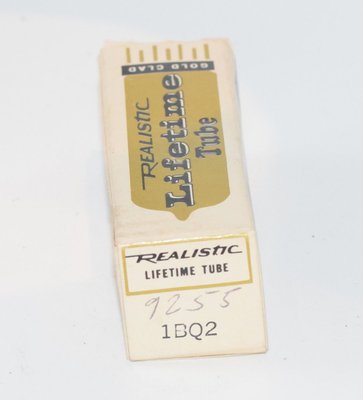
- Gold pin variants: Some NOS (New Old Stock) examples of the 1BQ2 are found with gold-plated pins, such as those sold under the Realistic (Radio Shack) brand. Gold plating was used to improve contact reliability and resist corrosion.
- Low interelectrode capacitance: The plate-to-all capacitance of just 1.0 pF minimizes capacitive coupling that could affect the high-voltage pulse waveform.
7. Usage in the Audio Community
The 1BQ2 has essentially no presence in the audio community. This is entirely expected given its design purpose and electrical characteristics:
- Voltage ratings are far too high: The 20 KV operating voltage is orders of magnitude beyond anything used in audio equipment. Even the most extreme audio amplifier designs rarely exceed 1,000 volts.
- Current capability is far too low: At 500 μA maximum average output current, the 1BQ2 cannot supply enough current to power even the most modest audio circuit.
- No amplification capability: As a simple diode, the 1BQ2 cannot be used as a voltage amplifier, driver, or output tube.
- No audio rectifier application: Audio power supply rectifiers (such as the 5U4, 5AR4/GZ34, 5Y3, or 6X4) operate at hundreds of volts and tens or hundreds of milliamps — a completely different operating regime from the 1BQ2.
The 1BQ2/DY802 is primarily of interest to:
- Vintage television restorers who need replacement EHT rectifiers for CRT television sets from the 1960s and 1970s.
- Tube collectors who seek complete collections of specific manufacturers' product lines.
- Electronics historians studying the evolution of television technology.
NOS (New Old Stock) examples of the 1BQ2 remain available from vintage electronics suppliers, including gold-pin variants from brands like Realistic. Prices are generally modest, as demand is limited to the restoration and collector markets. The tube is not sought after by audiophiles, guitar amplifier builders, or any segment of the audio community.
If you encounter a 1BQ2 in your tube collection, it is best appreciated as a fascinating piece of television engineering history — a tube designed to operate reliably at voltages that would be lethal to humans, in an environment (inside the television cabinet near the flyback transformer) that subjected it to extreme electrical stress, heat, and electromagnetic interference.