Introduction and History
The 1U4 is a miniature, filamentary, sharp-cutoff pentode vacuum tube designed primarily for radio-frequency (RF) and intermediate-frequency (IF) amplifier service in battery-operated receivers. Developed during the late 1940s and early 1950s — the golden era of portable tube radios — the 1U4 was part of a family of low-voltage, low-current tubes engineered to operate efficiently from dry-cell batteries, making portable radio reception practical before the widespread adoption of transistors.
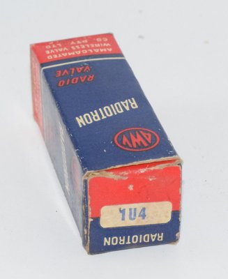
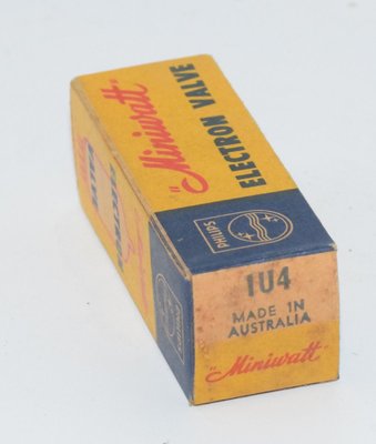
Manufactured by major companies including General Electric, RCA, Philips Miniwatt, and Radiotron (AWV), the 1U4 was a staple component in the compact "All American Five"-style battery portable radios of the 1950s. Its extremely low filament power consumption of only 70 milliwatts (1.4V at 50mA) made it ideal for sets powered by a single 1.5V "A" battery cell. The tube was documented in General Electric's ET-T1445 datasheet (dated April 1957, superseding ET-T234B from May 1950), confirming its long production life and widespread use.
The 1U4 belongs to the 1.4-volt filament battery tube series that also included types such as the 1R5 (converter), 1S5 (diode-pentode), 1T4 (pentode), and 3V4 (power pentode), which together formed complete superheterodyne receiver tube complements for portable radios.
Technical Specifications and Design
General Electrical Characteristics
| Parameter | Value |
|---|---|
| Tube Type | Sharp-Cutoff Pentode |
| Cathode Type | Coated Filament (directly heated) |
| Filament Voltage (DC) | 1.4 Volts |
| Filament Current | 0.05 Amperes (50 mA) |
| Filament Power | 70 mW |
Maximum Ratings (Design-Center Values)
| Parameter | Value |
|---|---|
| Maximum Plate Voltage | 110 Volts |
| Maximum Screen Voltage (Grid 2) | 110 Volts |
| Positive DC Grid-Number 1 Voltage | 0 Volts |
| DC Cathode Current (maximum) | 6.0 mA |
Note: The TDSL reference database lists maximum plate voltage and screen voltage as 120V. The General Electric ET-T1445 datasheet specifies design-center maximum ratings of 110V for both plate and screen. Designers should consult the specific manufacturer's datasheet for the tubes they are using, as ratings may vary slightly between manufacturers. The more conservative 110V GE rating is recommended for safe design practice.
Typical Operating Conditions — Class A1 Amplifier
| Parameter | Value |
|---|---|
| Plate Voltage | 90 Volts |
| Screen Voltage (Grid 2) | 90 Volts |
| Grid-Number 1 Voltage | 0 Volts |
| Plate Resistance (approximate) | 1.0 Megohm |
| Transconductance (gm) | 900 Micromhos (µS) |
| Plate Current | 1.6 mA |
| Screen Current | 0.5 mA |
| Grid-Number 1 Voltage for Ib = 10 µA (approximate cutoff) | −4 Volts |
Note: The amplification factor (µ) is not explicitly stated in the GE datasheet but can be estimated from the relationship µ = gm × rp. With gm = 900 µmhos and rp = 1.0 MΩ, the calculated µ is approximately 900. Maximum plate dissipation is not explicitly listed in the GE datasheet; however, with a maximum cathode current of 6.0 mA and maximum plate voltage of 110V, the practical plate dissipation limit should be confirmed against the specific manufacturer's data.
Direct Interelectrode Capacitances
| Capacitance | With External Shield* | Without Shield |
|---|---|---|
| Grid-Number 1 to Plate (Cga), maximum | 0.01 µµF (pF) | 0.01 µµF (pF) |
| Input (Cgk) | 3.6 µµF (pF) | 3.6 µµF (pF) |
| Output (Cak) | 7.5 µµF (pF) | 7.5 µµF (pF) |
* With external shield (RETMA 316) connected to pin 1.
Mechanical and Physical Details
| Parameter | Value |
|---|---|
| Base Type | E7-1, Miniature Button 7-Pin (B7G) |
| Basing Designation | RETMA 6AR |
| Envelope | T-5½, Glass |
| Mounting Position | Any |
| Maximum Overall Length | 1-7/8 inches |
| Maximum Diameter | 3/4 inch |
| Maximum Seated Height | 1-1/2 + 3/32 inches |
Pin Connections (RETMA 6AR Basing — Bottom View)
| Pin | Connection |
|---|---|
| Pin 1 | Negative Filament, Internal Shield, and Grid Number 3 (Suppressor) |
| Pin 2 | Plate |
| Pin 3 | Grid Number 2 (Screen) |
| Pin 4 | No Connection |
| Pin 5 | Negative Filament, Internal Shield, and Grid Number 3 (Suppressor) |
| Pin 6 | Grid Number 1 (Control Grid) |
| Pin 7 | Positive Filament |
Note: All voltages are referred to the negative terminal of the filament. Pins 1 and 5 are both connected to the negative filament, internal shield, and suppressor grid, providing a dual ground return path.
Class A Resistance-Coupled Amplifier Performance Data
The GE datasheet provides extensive performance data for resistance-coupled amplifier configurations at three B+ supply voltages (45V, 90V, and 135V). Representative examples at Ebb = 90 Volts:
| Rp (MΩ) | Rs (MΩ) | Rk (kΩ) | Rsg (kΩ) | Gain | Eo (V RMS) |
|---|---|---|---|---|---|
| 0.24 | 0.24 | 10 | — | 26 | 18 |
| 0.24 | 0.51 | 10 | 0.02 | 34 | 20 |
| 0.51 | 0.51 | 10 | — | 42 | 15 |
| 0.51 | 0.75 | 10 | — | 48 | 17 |
| 0.75 | 0.75 | 10 | — | 47 | 14 |
| 0.75 | 1.0 | 10 | — | 51 | 15 |
| 1.0 | 1.0 | 10 | — | 48 | 12 |
Notes: Eo is maximum RMS voltage output for 5% total harmonic distortion. Gain measured at 2.0 volts RMS output. For zero-bias data, generator impedance is negligible.
Applications and Usage
The 1U4 was designed and primarily used in the following applications:
- RF Amplifier Stages: In battery-operated superheterodyne receivers, the 1U4 served as the radio-frequency amplifier ahead of the converter stage, providing signal gain and improved selectivity.
- IF Amplifier Stages: The tube's sharp-cutoff characteristic and high gain made it well-suited for intermediate-frequency amplifier stages, typically at 455 kHz in standard AM broadcast receivers.
- Portable Battery Radios: The 1U4's extremely low filament power (70 mW) was specifically optimized for portable receivers powered by dry-cell batteries, where battery life was a critical design consideration.
- Resistance-Coupled Amplifiers: The datasheet provides extensive data for RC-coupled audio amplifier configurations, indicating the tube could also serve in low-level audio voltage amplifier stages.
- Military and Field Equipment: The tube's military equivalent designation CV2507 indicates its use in military communications equipment where battery operation was essential.
A typical battery portable radio of the 1950s might use the following tube complement: 1R5 (converter/mixer), 1U4 (IF amplifier), 1U5 or 1S5 (detector/AVC/audio), and 3V4 or 3S4 (audio output), all sharing a common 1.5V "A" battery for filaments and a 67.5V or 90V "B" battery for plate supply.
Sound Characteristics
The 1U4, being a sharp-cutoff pentode designed primarily for RF/IF service rather than audio amplification, has a distinctive sonic character when pressed into audio duty:
- Clean and Transparent at Low Levels: Operating at very low plate currents (1.6 mA typical), the 1U4 produces a clean, transparent sound when used as a voltage amplifier within its linear operating range. The high plate resistance of 1.0 MΩ gives it a characteristically "airy" quality.
- Sharp Cutoff Character: Unlike remote-cutoff (variable-mu) pentodes, the 1U4's sharp-cutoff characteristic means it transitions relatively abruptly from linear operation to clipping. This gives it a more defined, less gradual distortion onset compared to variable-mu types.
- Pentode Brightness: Like most pentodes used in audio, the 1U4 tends toward a brighter, more harmonically complex tonal character compared to triodes. The high plate resistance means it is sensitive to load impedance, and the tonal balance can shift significantly depending on the plate load resistor value.
- Microphonic Sensitivity: Being a miniature tube with a directly-heated filament, the 1U4 can exhibit some microphonic behavior, which in audio applications can add a subtle "liveness" or, if excessive, unwanted ringing.
- Low Headroom: With maximum output voltages in the range of 12–34 volts RMS (depending on circuit configuration and B+ voltage), the 1U4 has limited headroom. This can result in soft, musical compression when driven hard, though the sharp-cutoff nature means the onset of clipping is more abrupt than with variable-mu pentodes.
- Quiet Operation: The very low grid-to-plate capacitance of 0.01 pF and the internal shielding contribute to low noise floor when properly implemented, making it suitable for high-gain, low-signal applications.
Equivalent and Substitute Types
| Type | Relationship | Notes |
|---|---|---|
| CV2507 | Direct equivalent | British military (Common Valve) designation for the 1U4. Fully interchangeable, identical pinout and specifications. |
| 1T4 / DF91 | Similar but not identical | The 1T4 is a closely related 1.4V filament pentode from the same family, but it is a remote-cutoff (variable-mu) type rather than sharp-cutoff. It shares the same filament ratings and base type but has different gain characteristics. Not a direct substitute in AGC-controlled IF stages where sharp cutoff is required, but may work in some RF amplifier applications. |
| DF96 | Functional equivalent (European) | European equivalent designed for similar battery-operated applications, but pin connections and some specifications differ. Not a direct plug-in replacement without circuit modification. |
Note: When substituting tubes, always verify pinout compatibility and operating conditions. The 1U4's sharp-cutoff characteristic is a key design parameter — substituting a remote-cutoff type like the 1T4 will change the AGC behavior and gain characteristics of the circuit.
Notable Characteristics
- Extremely Low Power Consumption: At only 70 mW filament power and approximately 190 mW total plate/screen dissipation at typical operating conditions, the 1U4 is one of the most power-efficient amplifying tubes ever produced. Total tube power consumption is well under 300 mW.
- Sharp-Cutoff Design: The sharp-cutoff characteristic (Ib = 10 µA at approximately −4V grid bias) makes the 1U4 particularly suitable for IF amplifier stages where consistent gain is desired without AGC, or where a well-defined cutoff point is needed.
- Internal Shielding: The 1U4 features an internal shield connected to pins 1 and 5 (negative filament), providing excellent isolation between input and output circuits. The grid-to-plate capacitance of only 0.01 pF is remarkably low, minimizing feedback and ensuring stable high-frequency operation.
- Suppressor Grid Connection: The suppressor grid (Grid Number 3) is internally connected to the negative filament terminal and the internal shield, simplifying external circuit connections.
- Dual Filament Return Pins: Both pins 1 and 5 connect to the negative filament, providing a low-inductance return path and improved RF grounding — an important consideration for stable high-frequency operation.
- High Plate Resistance: The 1.0 MΩ plate resistance is characteristic of a pentode with high amplification factor, making the tube's gain relatively independent of plate load resistance (up to a point) but also making it sensitive to plate load for frequency response shaping.
- Versatile Supply Voltage Range: The datasheet provides performance data for B+ voltages from 45V to 135V, demonstrating the tube's ability to operate effectively across a wide range of battery supply voltages as batteries age and voltage drops.
- High Voltage Gain: Despite its tiny size and minimal power consumption, the 1U4 can achieve voltage gains of up to 108 in resistance-coupled amplifier configurations at 135V B+ supply.
Usage in the Audio Community
While the 1U4 was never designed as an audio tube, it has found a niche following in several areas of the audio community:
Battery-Powered Headphone Amplifiers
The 1U4's ultra-low filament requirements make it a natural choice for DIY battery-powered tube headphone amplifiers. Hobbyists have built compact, portable headphone amps using one or two 1U4 tubes powered by a single AA or C cell for the filament and a small stack of 9V batteries or a boost converter for the B+ supply. These designs appeal to audiophiles who want the "tube sound" in a portable format.
Micro-Power Tube Audio Projects
The maker and DIY audio community has embraced the 1U4 and its battery-tube siblings for ultra-low-power audio projects. Complete amplifier circuits consuming less than half a watt of total power can be built, making solar-powered or battery-powered tube audio systems practical. These projects often pair the 1U4 as a voltage amplifier/driver with a 3V4 or 3S4 output tube.
Crystal Radio and Regenerative Receiver Audio
Audio enthusiasts interested in vintage radio reception use the 1U4 in regenerative receiver designs where its high gain and sharp-cutoff characteristic provide excellent sensitivity and selectivity. The audio output from these receivers, while modest in power, has a characteristic warmth that enthusiasts find appealing for casual listening.
Guitar Effects and Experimental Audio
Some experimental guitar pedal builders have incorporated the 1U4 into battery-powered tube overdrive and boost pedals. The tube's ability to operate at relatively low B+ voltages (45V or even lower with reduced performance) makes it more practical for pedal applications than tubes requiring higher voltages. The sharp-cutoff characteristic provides a distinctive clipping character.
Vintage Radio Restoration
The primary audio community use of the 1U4 remains in the restoration and operation of vintage 1950s portable battery radios. Collectors and vintage audio enthusiasts seek out NOS (New Old Stock) 1U4 tubes from manufacturers like Philips Miniwatt, Radiotron (AWV), GE, RCA, and Sylvania to restore these classic receivers to working condition. The sound quality of a properly restored battery portable radio, while limited in bandwidth and power, has a nostalgic charm that many find appealing.
Availability and Collecting
NOS 1U4 tubes remain reasonably available from vintage tube dealers, as large quantities were manufactured during the 1950s. Philips Miniwatt and Radiotron AWV examples are particularly sought after by collectors. The CV2507 military equivalent can sometimes be found at lower prices and offers identical performance. As with all NOS battery tubes, testing before use is recommended, as filament integrity can degrade over decades of storage.