1. Introduction and History
The 1U5 is a miniature diode-pentode vacuum tube (valve) manufactured by General Electric and other major tube producers during the early 1950s. Designed specifically for compact, battery-operated portable receivers, the 1U5 combines a sharp-cutoff pentode amplifier section with a diode detector section in a single miniature glass envelope. This dual-function design was a hallmark of the post-war era's push toward smaller, more efficient portable radio designs that could operate from low-voltage battery supplies.
The tube was developed as part of the 1.4-volt filament family of tubes — a series specifically engineered to run directly from a single dry cell. This family included types like the 1R5 (converter), 1T4 (IF amplifier), 1S5 (diode-pentode), and 3V4/3S4 (output), which together formed complete superheterodyne receiver lineups for portable radios. The 1U5 served as a combined detector, audio-frequency amplifier, and automatic-volume-control (AVC) tube in these sets.
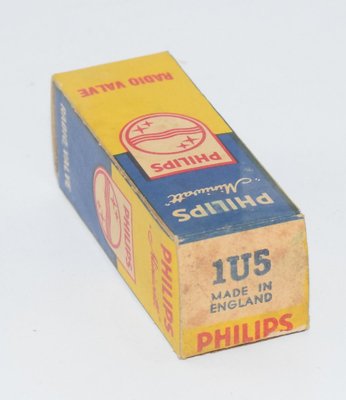
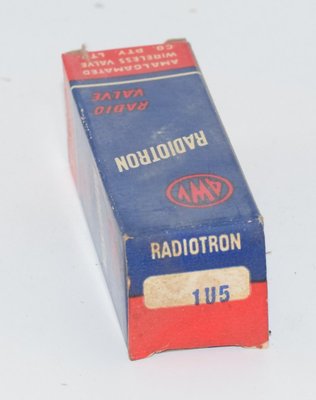
The General Electric datasheet (ET-T533B, dated 6-53, superseding ET-T533A dated 4-50) provides the definitive specifications for this tube. The 1U5 was widely produced by manufacturers including GE, Philips Miniwatt (including their UK Mitcham factory), AWV (Amalgamated Wireless Valve Company, marketed under the Super Radiotron brand in Australia), and others. Its military equivalent is designated CV3912.
A key design feature noted in the GE datasheet is that the diode section is effectively shielded from the pentode section to reduce feed-through effects, an important consideration for maintaining clean detection and AVC performance in sensitive receiver circuits.
2. Technical Specifications and Design
General Characteristics
| Parameter | Value |
| Tube Type | Diode-Pentode (Sharp-Cutoff Pentode) |
| Cathode Type | Coated Filament (directly heated) |
| Filament Voltage (D-C) | 1.4 Volts |
| Filament Current | 0.05 Ampere (50 mA) |
| Envelope | T-5½, Glass |
| Base | E7-1, Miniature Button 7-Pin (B7G) |
| Mounting Position | Any |
| RTMA Basing | 6BW |
| Physical Dimensions | ¾" max diameter × 2⅝" max seated height |
Maximum Ratings (Design-Center Values)
| Parameter | Maximum Value |
| Plate Voltage | 90 Volts |
| Screen Voltage (Grid Number 2) | 90 Volts |
| Positive D-C Grid-Number 1 Voltage | 0 Volts |
| Negative D-C Grid-Number 1 Voltage | 50 Volts |
| D-C Cathode Current | 3.0 Milliamperes |
| Diode Current for Continuous Operation | 0.25 Milliampere |
Note: The TDSL reference data lists Va(max) and Vg2(max) as 100V. The GE datasheet specifies 90V for both plate and screen as design-center maximum ratings. Builders should use the more conservative 90V figure from the manufacturer datasheet for safe operation, though some sources may rate the tube to 100V under certain conditions.
Direct Interelectrode Capacitance
| Parameter | With Shield* | Without Shield |
| Diode Plate to Grid-Number 1, maximum | 0.04 µµf | 0.04 µµf |
* With external shield (RTMA 316) connected to pin 1.
Characteristics and Typical Operation — Class A₁ Amplifier
| Parameter | Value |
| Plate Voltage | 67.5 Volts |
| Screen Voltage | 67.5 Volts |
| Grid-Number 1 Voltage | 0 Volts |
| Plate Resistance, approximate | 0.6 Megohm (600 kΩ) |
| Transconductance (gm) | 625 Micromhos (µS) |
| Plate Current | 1.6 Milliamperes |
| Screen Current | 0.4 Milliampere |
| Grid-Number 1 Voltage, approximate (Ib = 10 µA) | -5 Volts |
Amplification Factor (µ): The amplification factor can be estimated from the relationship µ = gm × rp. With gm = 625 µmhos and rp = 0.6 MΩ, µ ≈ 375. This is a calculated value; confirm against additional manufacturer data if critical precision is required.
Maximum Plate Dissipation: The GE datasheet does not explicitly state a maximum plate dissipation figure. However, based on the maximum ratings (90V plate, 3.0 mA total cathode current), the plate dissipation under maximum conditions would be modest — well under 0.5 watts. This value should be confirmed against additional manufacturer documentation.
Diode Section
| Parameter | Value |
| Average Diode Current (with 10V D-C applied) | 1.5 Milliamperes |
| Maximum Continuous Diode Current | 0.25 Milliampere |
Note: The diode is located at the negative end of the filament. All voltages are referred to the negative terminal of the filament.
Class A Resistance-Coupled Amplifier Data
The GE datasheet provides extensive resistance-coupled amplifier design data at three B+ supply voltages (45V, 90V, and 135V) with various plate and screen resistor combinations. Representative examples at Ebb = 90 Volts:
| Rp (MΩ) | Rs (MΩ) | Rg1 (MΩ) | Rk (kΩ) | Rsg (kΩ) | Gain | Eo (V RMS) |
| 0.24 | 0.24 | — | — | 0.8 | 29 | 13 |
| 0.51 | 0.51 | — | — | 1.9 | 40 | 12 |
| 0.75 | 0.75 | — | — | 2.9 | 47 | 11 |
| 1.0 | 1.0 | — | — | 3.9 | 50 | 9 |
Notes from datasheet: Eo is maximum RMS voltage output for 5% total harmonic distortion. Gain measured at 2.0 volts RMS output. For zero-bias data, generator impedance is negligible.
Pin Connections (RTMA 6BW — Bottom View)
| Pin | Connection |
| Pin 1 | Negative Filament and Grid Number 3 (Suppressor) |
| Pin 2 | Plate |
| Pin 3 | Grid Number 2 (Screen) |
| Pin 4 | Diode Plate† |
| Pin 5 | No Connection |
| Pin 6 | Grid Number 1 (Control Grid) |
| Pin 7 | Positive Filament |
† The diode is located at the negative end of the filament.
3. Applications and Usage
The 1U5 was designed primarily for three simultaneous functions in battery-operated portable superheterodyne receivers:
- Signal Detection: The diode section serves as an AM detector, rectifying the intermediate-frequency (IF) signal to recover the audio modulation.
- Audio-Frequency Amplification: The pentode section amplifies the detected audio signal in a Class A₁ resistance-coupled configuration, driving the output stage (typically a 3V4 or 3S4).
- Automatic Volume Control (AVC): The diode section simultaneously develops a DC voltage proportional to the signal strength, which is fed back to the IF amplifier stage (typically a 1T4) to maintain consistent volume across varying signal strengths.
A typical battery portable receiver lineup using the 1U5 would be:
- 1R5 — Pentagrid converter (mixer/oscillator)
- 1T4 — IF amplifier
- 1U5 — Detector, AVC, and first audio amplifier
- 3V4 or 3S4 — Audio output
This combination was extremely popular in the late 1940s and throughout the 1950s in countless portable radio designs from manufacturers worldwide. The entire receiver could operate from a single 1.5V "A" cell (for filaments) and a 67.5V or 90V "B" battery (for plate supply), making truly portable radio reception practical.
The 1U5 can also be operated in triode connection (screen tied to plate), as shown in the GE datasheet's triode-connection plate characteristics. In this mode, the tube exhibits lower gain but potentially lower distortion characteristics suitable for certain circuit topologies.
4. Sound Characteristics
The 1U5, being a low-power battery pentode operating at modest voltages and currents, has a distinctive sonic character that is quite different from the more commonly discussed audio tubes:
- Warm and Intimate: Operating at very low plate voltages (typically 45–90V) and minimal current, the 1U5 produces a characteristically warm, soft sound. The low operating voltages contribute to a gentle, rounded tonal quality that many listeners find appealing for intimate listening.
- Midrange Presence: Like many small-signal pentodes of this era, the 1U5 exhibits a pronounced midrange character. Vocals and acoustic instruments are rendered with a pleasant presence and clarity that is well-suited to the AM broadcast content it was designed to reproduce.
- Soft Clipping: When driven into distortion, the 1U5 clips relatively gently, producing predominantly even-order harmonics (especially in triode-connected mode). This soft clipping behavior is musically pleasant and forgiving, contributing to the "vintage radio" sound that many enthusiasts find charming.
- Limited Bandwidth: The relatively high plate resistance (0.6 MΩ) combined with typical circuit capacitances naturally rolls off the high-frequency response. This gives the 1U5 a naturally warm, non-fatiguing character but limits its suitability for high-fidelity applications requiring extended treble response.
- Low Noise Floor: The directly-heated filament, while potentially introducing some hum in AC-powered applications, runs on DC in its intended battery service, resulting in an exceptionally quiet noise floor. The low transconductance (625 µmhos) also contributes to relatively low microphonic sensitivity compared to higher-gain tubes.
- Gentle Dynamics: With modest gain (up to about 50 in resistance-coupled circuits at 90V) and limited headroom, the 1U5 compresses dynamics gently. This compression is subtle and musical, adding a cohesive quality to the sound that can be pleasing for certain applications.
In triode-connected mode (screen tied to plate), the sound becomes even warmer and more linear, with reduced gain but improved distortion characteristics. The triode curves shown in the datasheet reveal smooth, evenly-spaced characteristics that suggest good linearity in this configuration.
5. Equivalent or Substitute Types
| Type | Relationship | Notes |
| CV3912 | Direct equivalent (military designation) | Identical specifications; direct drop-in replacement. This is the UK military (Common Valve) designation for the 1U5. |
| 1S5 | Similar but NOT identical | The 1S5 is also a diode-pentode in the 1.4V filament family with the same base, but it is a remote-cutoff (variable-mu) pentode, whereas the 1U5 is a sharp-cutoff pentode. The 1S5 was designed for combined IF amplifier/detector/AVC service where variable-mu characteristics are needed. They are NOT directly interchangeable in all circuits due to the different cutoff characteristics, though in some detector/audio applications the substitution may work acceptably. |
| DAF91 | European equivalent of the 1S5 | Same caveats as the 1S5 — remote-cutoff vs. sharp-cutoff difference. Not a direct substitute for the 1U5. |
Note: Builders should exercise caution when substituting tubes in this family. While the 1U5 and 1S5 share the same base, filament ratings, and general function, the sharp-cutoff vs. remote-cutoff distinction is significant and can affect circuit performance, particularly in AVC-controlled stages. The CV3912 is the only verified direct/identical substitute.
6. Notable Characteristics
- Effective Internal Shielding: The GE datasheet specifically notes that the diode section is effectively shielded from the pentode section. This is a significant design feature that reduces unwanted coupling between the detector and amplifier functions, improving overall receiver performance and reducing distortion caused by feed-through effects.
- Extremely Low Power Consumption: With a filament drawing only 50 mA at 1.4V (70 mW filament power) and total cathode current limited to 3.0 mA, the 1U5 is remarkably frugal. This made extended battery life possible in portable receivers — a critical selling point in the pre-transistor era.
- Sharp-Cutoff Pentode: Unlike the remote-cutoff 1S5, the 1U5's sharp-cutoff characteristic means the tube transitions relatively abruptly from conducting to non-conducting as the grid voltage becomes more negative. The datasheet shows the tube reaching approximately 10 µA plate current at -5V grid bias (with 67.5V on plate and screen). This sharp cutoff is advantageous for audio amplification where consistent gain is desired regardless of AVC voltage variations.
- Versatile Operating Range: The resistance-coupled amplifier data shows the tube performing well across a wide range of B+ voltages (45V to 135V) and load conditions, making it adaptable to various battery configurations commonly available in the 1950s.
- Triode Connection Capability: The datasheet includes triode-connection plate characteristics (screen tied to plate), showing the tube can function as a triode with smooth, well-behaved curves up to 200V plate voltage. This versatility extends the tube's usefulness beyond its primary pentode application.
- Low Interelectrode Capacitance: The diode-to-grid capacitance of only 0.04 µµf (pF) — identical with or without an external shield — demonstrates the effectiveness of the internal shielding and ensures minimal unwanted coupling at IF frequencies.
- Universal Mounting: The tube can be mounted in any position, providing maximum flexibility for compact receiver chassis layouts.
7. Usage in the Audio Community
The 1U5 occupies a niche but enthusiastic corner of the audio community, primarily in the following contexts:
Vintage Radio Restoration
The most common use of the 1U5 today is in the restoration and maintenance of vintage battery-operated portable radios from the late 1940s and 1950s. Collectors and restorers of sets by Zenith, Emerson, Admiral, Motorola, and other manufacturers of the era frequently need 1U5 tubes. NOS (New Old Stock) examples from manufacturers like GE, Philips Miniwatt, and AWV Super Radiotron remain available through specialty tube dealers, though supplies are gradually diminishing.
Low-Voltage Tube Audio Projects
The 1U5 has found a following among DIY audio enthusiasts who build low-voltage, battery-powered tube amplifiers and headphone amplifiers. The 1.4V filament requirement means the tube can be powered by a single AA or C cell, and the low B+ requirements (as low as 45V) make safe, compact builds possible. These "starved plate" or "low-voltage" tube projects have become increasingly popular as hobbyists seek the tube sound in portable or desktop-friendly formats.
Typical DIY projects using the 1U5 include:
- Battery-powered headphone amplifiers: Using the pentode section as a voltage amplifier driving high-impedance headphones.
- Crystal radio amplifiers: Adding one or two stages of amplification to a crystal detector for loudspeaker-level output.
- Miniature guitar practice amplifiers: Exploiting the tube's soft clipping characteristics for pleasant overdrive tones at very low volumes.
- Cigar-box radios and novelty builds: The tiny T-5½ envelope and low power requirements make the 1U5 ideal for compact, visually appealing builds.
Educational Use
The 1U5 and its companion tubes in the 1.4V filament family are popular for educational purposes. The low voltages involved (both filament and B+) make these tubes significantly safer for beginners learning about vacuum tube circuits compared to tubes requiring hundreds of volts. The complete superheterodyne receiver that can be built with the 1R5/1T4/1U5/3V4 lineup provides an excellent hands-on learning platform for understanding radio receiver principles.
Collectibility
Among tube collectors, the 1U5 is moderately collectible. Particularly sought-after are examples from specific manufacturers or factories — Philips Miniwatt tubes from the UK Mitcham factory and AWV Super Radiotron examples from Australia carry a premium among collectors who value provenance and construction quality. Military-spec CV3912 examples are also prized for their typically tighter manufacturing tolerances and rugged construction.
Limitations in Modern Audio Use
It should be noted that the 1U5 has significant limitations for high-fidelity audio applications. The high plate resistance (0.6 MΩ), modest transconductance (625 µmhos), and low maximum plate voltage (90V) mean that the tube cannot drive low-impedance loads effectively and has limited output voltage swing. The bandwidth is inherently restricted, and the gain, while respectable for a battery tube, is modest compared to more common audio pentodes like the EF86 or 6AU6. These characteristics, however, are precisely what endear the tube to enthusiasts seeking a particular vintage sonic character rather than audiophile-grade specifications.