1. Introduction and History
The Type 280 vacuum tube, also known as the UX-280 or simply the '80', is a full-wave rectifier tube that played a crucial role in the development of early electronic equipment. Introduced in the late 1920s by RCA, the 280 became one of the most widely used rectifier tubes in radio receivers and audio amplifiers during the golden age of vacuum tube technology.
The 280 was developed as power requirements for radio receivers grew beyond what earlier rectifiers could handle. It was designed to provide the necessary DC power for the increasingly complex and power-hungry radio sets of the era. The tube was part of the UX series, which featured the standard UX four-pin base that became an industry standard.
Production of the 280 began around 1927 and continued for decades, with various manufacturers producing their own versions of this essential component. The tube's reliability and efficiency made it a staple in power supplies until solid-state rectifiers began to replace vacuum tube technology in the 1960s.
2. Technical Specifications and Design
The 280 is a directly heated, full-wave rectifier vacuum tube with the following specifications:
- Filament Voltage: 5.0 volts
- Filament Current: 2.0 amperes
- Maximum AC Voltage Per Plate: 350-400 volts RMS
- Maximum DC Output Current: 125 mA
- Voltage Drop: Approximately 60 volts at full load
- Base: 4-pin UX (medium)
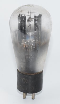
- Envelope: ST-shaped glass (balloon style in early versions)
- Internal Structure: Two separate plates surrounding a central filament
The 280 features a distinctive design with two separate plates (anodes) that are positioned on either side of a directly heated cathode (filament). This arrangement allows the tube to conduct on alternate half-cycles of the AC input, effectively converting AC to pulsating DC. The output is then typically filtered using capacitors and chokes to provide smooth DC voltage for the rest of the circuit.
The early versions of the 280, often referred to as "balloon tubes," featured a larger, rounded glass envelope. Later versions adopted the more standardized ST (shoulder type) glass shape, which was more compact while maintaining the same electrical characteristics.
3. Applications and Usage
The 280 rectifier tube found widespread use in various electronic applications:
- Radio Receivers: The 280 was commonly used in AC-powered radio receivers from the late 1920s through the 1940s, providing the necessary DC power for the set's vacuum tubes.
- Audio Amplifiers: Many early audio amplifiers, particularly those used in radio-phonograph combinations, utilized the 280 in their power supplies.
- Test Equipment: Various test instruments and laboratory equipment employed the 280 for power rectification.
- Early Television Receivers: Some early television sets used the 280 or its derivatives in their power supplies.
In a typical application, the 280 would be connected to the secondary winding of a power transformer. The center tap of this winding would be connected to ground (often through a resistor to develop bias voltages), while the two ends of the winding would connect to the two plates of the 280. The filament would be powered by a separate 5V winding on the transformer. The rectified DC output would then be taken from the cathode of the tube and filtered through a network of capacitors and chokes to provide smooth DC voltage.
4. Equivalent or Substitute Types
Several tubes can serve as direct or near-direct replacements for the 280:
- 5Y3: The most common replacement, with nearly identical characteristics but slightly lower current capability (125mA vs. 110mA).
- 5Y3GT: A more modern version with the same electrical characteristics in a smaller glass envelope.
- 5U4: Can replace the 280 in applications requiring higher current, offering up to 225mA output.
- 5V4G/5AZ4: An indirectly heated replacement with lower voltage drop, suitable for most 280 applications.
- 5AR4/GZ34: A more modern replacement with lower voltage drop, useful in applications where higher voltage output is desired.
- 83: A mercury vapor version of the 280 with lower voltage drop but requiring special handling due to its mercury content.
When substituting tubes, it's important to consider not just the electrical characteristics but also the physical dimensions and heat dissipation requirements, as these can affect the performance and reliability of the equipment.
5. Notable Characteristics
The 280 vacuum tube has several distinctive characteristics that are worth noting:
- Warm-up Time: As a directly heated tube, the 280 reaches operating temperature quickly, typically within a few seconds.
- Blue Glow: During operation, the 280 often exhibits a characteristic blue glow around the plates. This is normal and is caused by ionization of residual gases within the tube.
- Voltage Drop: The 280 has a relatively high voltage drop (about 60 volts at full load), which reduces the available B+ voltage and generates significant heat.
- Ruggedness: The 280 is known for its durability and long service life when operated within specifications.
- Inrush Current: When first powered on, the cold filament of the 280 presents a low resistance, resulting in a high initial current surge that can stress power transformers.
- Collector Value: Early balloon-type 280 tubes, especially those with clear glass and visible internal structures, are sought after by collectors of vintage radio equipment.
The 280's relatively high internal resistance and voltage drop made it less than ideal for high-power applications, which led to the development of improved rectifiers like the 5U4 and eventually solid-state alternatives. However, the characteristic sound of equipment using 280 rectifiers—partly due to the tube's specific voltage regulation properties—remains appreciated by audio enthusiasts and is sometimes deliberately sought in vintage and boutique audio equipment designs.
For restoration of vintage equipment originally designed with the 280, using the correct tube type or an appropriate substitute is important not only for authentic operation but also for ensuring proper loading of the power transformer and correct voltages throughout the circuit.