1. Introduction and History
The 2C26 is an ultra-high-frequency triode designed primarily for use as a grid pulse or plate pulse oscillator at frequencies up to 300 megacycles (MHz). Developed during World War II, the 2C26 was manufactured by several American companies, including Hytron Corporation of Salem, Massachusetts, and Radio Receptor Co. The tube was released under RMA (Radio Manufacturers Association) specifications and saw extensive use in military radar, communications, and pulse-generation equipment during the 1940s.
The 2C26 was part of a family of specialized UHF triodes developed to meet the wartime demand for reliable, high-frequency oscillator tubes capable of delivering high peak plate currents in pulsed operation. Its cathode was specifically designed and processed to withstand the extreme demands of pulse service, and its top-cap construction was engineered to permit operation at maximum ratings without external voltage breakdown, even at higher altitudes — a critical requirement for airborne military equipment.
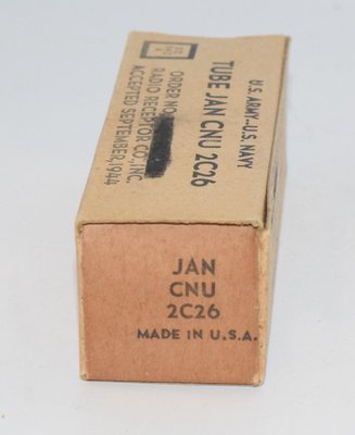
An improved version, the 2C26A, was subsequently released by Hytron (RMA Release No. 333A, dated September 27, 1944). The 2C26A is noted as being interchangeable with and a replacement for the original 2C26, though it carries different maximum ratings, particularly regarding plate and grid pulse potentials. The 2C26A's top cap design was specifically enhanced for high-altitude operation. Production examples from Radio Receptor Co. dated 1944 are known to exist as NOS (New Old Stock) US Army surplus, confirming the tube's military provenance.
2. Technical Specifications and Design
The following specifications are drawn from the Hytron 2C26A datasheet (RMA Release 333A, September 27, 1944). Since the 2C26A is stated to be interchangeable with and a replacement for the 2C26, these specifications are representative of the type. Note that the original 2C26 may have slightly lower maximum ratings in certain parameters (the 2C26A is listed as a "different rating substitute" rather than a drop-in identical type); where original 2C26-specific data differs, this is noted.
Electrical Specifications
| Parameter | Value |
|---|---|
| Cathode Type | Coated Unipotential (Indirectly Heated) |
| Heater Voltage | 6.3 V |
| Heater Current | 1.1 A |
| Plate Dissipation (max) | 10 W |
| Grid Dissipation (max) | 2.5 W |
| Plate Potential (plate pulsed, max peak) | 3500 V |
| Plate Potential (grid pulsed, max DC) | 2500 V |
| Grid Bias (max DC) | −700 V |
| Frequency for Maximum Rating | 300 MC (MHz) |
Average Characteristics (Eb = 400 V; Ec = −15 V; Eh = 6.3 V)
| Parameter | Value |
|---|---|
| Plate Current | 16 mA |
| Amplification Factor (μ) | 16.3 |
| Transconductance (gm) | 2250 μmhos |
| Plate Resistance (rp) — calculated | ~7,244 Ω (derived from μ/gm = 16.3/0.00225) |
Note: Plate resistance (rp) is not explicitly stated in the datasheet but is calculated from the relationship rp = μ / gm. The calculated value of approximately 7.2 kΩ should be confirmed against additional manufacturer data if critical precision is required.
Average Direct Inter-electrode Capacitances
| Capacitance | Value |
|---|---|
| Grid-to-Plate (Cgp) | 2.8 pF (mmf) |
| Grid-to-Cathode (Cgk) | 2.6 pF (mmf) |
| Plate-to-Cathode (Cpk) | 1.1 pF (mmf) |
Mechanical Specifications
| Parameter | Value |
|---|---|
| Cooling | Convection (natural air cooling) |
| Base | Intermediate shell, Octal 8-pin phenolic |
| Top Caps | Special skirted miniature with insulating bushing |
| Bulb | T-9 |
| Length (max overall) | 3-11/16 inches |
| Seated Height | 3-1/8 inches |
| Diameter (max) | 1-5/16 inches |
| Net Weight | 1-1/2 ounces |
Pin-Out (Octal Base — Bottom View)
Based on the Hytron basing diagram:
- Pin 1: No connection (or internal shield — confirm against specific manufacturer)
- Pin 2: Heater
- Pin 3: Heater
- Pin 4: Connected (see basing diagram)
- Pin 5: Connected (see basing diagram)
- Pin 6: Connected (see basing diagram)
- Pin 7: Heater return / Cathode
- Pin 8: Connected (see basing diagram)
- Top Cap(s): Plate and Grid connections brought out to top caps
Note: The 2C26/2C26A uses a dual top-cap arrangement for the plate and grid connections. This is a critical design feature that reduces inter-electrode capacitance and permits operation at UHF frequencies without voltage breakdown. The exact pin assignments for cathode, heater, and internal connections should be verified against the specific manufacturer's basing diagram before use. The Hytron datasheet shows the bottom-view basing connections with pins numbered 1 through 8 in the standard octal arrangement.
3. Applications and Usage
The 2C26 was designed for specialized high-frequency and pulse applications:
- UHF Pulse Oscillators: The primary intended application. The tube was designed to generate high-power pulses at frequencies up to 300 MHz, making it ideal for radar transmitter stages and military communications equipment.
- Grid Pulse Oscillator: In this mode, the tube is biased beyond cutoff and driven into conduction by positive grid pulses, generating bursts of RF energy at the resonant frequency of the plate circuit.
- Plate Pulse Oscillator: The plate voltage is pulsed on and off, with the tube oscillating only during the pulse-on period. The 2C26's cathode was specifically processed to deliver the extremely high peak plate currents required in this mode.
- Military Radar Systems: The tube's high-altitude voltage breakdown resistance and rugged construction made it suitable for airborne radar equipment during WWII.
- UHF Transmitters: Used in low-power UHF transmitter stages where frequencies up to 300 MHz were required.
- Laboratory RF Oscillators: The tube's well-characterized performance at UHF made it useful in test and measurement equipment.
The 2C26 was not originally designed for audio applications. Its design priorities — low inter-electrode capacitance, high-frequency capability, pulse handling, and high-altitude voltage integrity — reflect its military UHF origins rather than audio fidelity considerations.
4. Sound Characteristics
The 2C26 is an uncommon tube in audio circles, and detailed subjective listening evaluations are rare. However, based on its electrical characteristics and the experiences of experimenters who have used similar UHF triodes in audio circuits, the following observations can be made:
- Moderate Mu, Moderate Gain: With an amplification factor of 16.3 and transconductance of 2250 μmhos, the 2C26 falls in a middle ground — not a high-mu voltage amplifier and not a low-mu power tube. In audio driver or preamplifier stages, this would tend to produce a balanced, neither overly bright nor overly warm tonal character.
- Low Inter-electrode Capacitances: The very low capacitances (Cgp of 2.8 pF, Cgk of 2.6 pF, Cpk of 1.1 pF) suggest excellent high-frequency extension and transient response if used in an audio circuit. The tube should exhibit minimal Miller effect capacitance multiplication, preserving treble detail and air.
- Moderate Plate Resistance: The calculated plate resistance of approximately 7.2 kΩ is moderate, suggesting reasonable damping characteristics and compatibility with a range of load impedances.
- Pulse-Optimized Cathode: The cathode's design for high peak current delivery in pulse service suggests robust emission capability, which in audio terms could translate to good dynamic headroom and clean transient handling.
- Expected Tonal Profile: Experimenters working with similar military UHF triodes in audio applications generally report a clean, detailed, and somewhat lean sound compared to classic audio triodes like the 2A3 or 300B. The emphasis tends to be on clarity and speed rather than warmth and richness. Midrange reproduction is typically articulate, and the high-frequency response is extended.
It should be noted that the 2C26 was never intended for audio use, and its sonic characteristics in audio circuits are largely anecdotal. Any audio application would be experimental in nature.
5. Equivalent or Substitute Types
| Type | Relationship | Notes |
|---|---|---|
| CV802 | Close/identical substitute | British military (CV-series) designation. Considered directly interchangeable with the 2C26. Drop-in replacement with identical pinout and ratings. |
| 2C26A | Different rating substitute (NOT a drop-in identical type) | Improved version by Hytron with enhanced top-cap design for high-altitude operation. Interchangeable with and replaces the 2C26 per Hytron's datasheet, but carries different maximum ratings. The 2C26A may have higher pulse voltage ratings than the original 2C26. Pin-compatible. |
| CV1759 | Different rating substitute (NOT a drop-in identical type) | British military designation. Related type with different ratings. Not a direct drop-in replacement; verify specifications before substitution. |
Important: While the 2C26A is stated by Hytron to be interchangeable with the 2C26, the TDSL database classifies it as a "different rating substitute" rather than an identical type. This suggests that while the tubes are pin-compatible and functionally interchangeable, their maximum ratings differ. The CV802 is the only confirmed close/identical substitute for the 2C26.
6. Notable Characteristics
- Dual Top-Cap Design: The 2C26 uses a distinctive dual top-cap arrangement for the plate and grid connections. This is unusual among octal-based tubes and was essential for achieving low inter-electrode capacitance and preventing voltage breakdown at UHF frequencies. The top caps use special skirted miniature connectors with insulating bushings.
- High-Altitude Operation: The 2C26A variant was specifically designed to operate at maximum ratings without external voltage breakdown at higher altitudes, where reduced air pressure lowers the breakdown voltage between external conductors. This was a critical requirement for airborne military equipment.
- Extreme Pulse Capability: The tube can handle plate pulse potentials up to 3500 V peak and grid pulse potentials up to 2500 V DC — remarkably high values for a tube of this physical size (T-9 envelope, 1.5 ounces). This reflects the specialized cathode processing for high peak current delivery.
- 300 MHz Frequency Rating: The 300 MC maximum frequency rating was exceptional for a tube of this era and size, placing it firmly in the UHF category.
- Wartime Production: The 2C26 is a product of the intense WWII-era development of radar and UHF communications technology. Known manufacturers include Hytron Corporation and Radio Receptor Co., both producing for US military contracts.
- Compact and Lightweight: At just 3-11/16 inches in length and 1-1/2 ounces, the 2C26 is a compact tube, well-suited to the space and weight constraints of military airborne equipment.
- Coated Unipotential Cathode: The indirectly heated cathode with its specialized coating was a key engineering feature, enabling the high peak emission currents required for pulse oscillator service.
7. Usage in the Audio Community
The 2C26 occupies a niche position in the audio community — it is not a mainstream audio tube by any measure, but it has attracted the attention of a small number of experimenters and DIY audio enthusiasts for several reasons:
Experimental and DIY Projects
The 2C26's moderate amplification factor (μ = 16.3) and reasonable transconductance (2250 μmhos) make it theoretically usable as a driver tube or even in small single-ended triode (SET) amplifier experiments. Its 10-watt plate dissipation rating provides enough thermal headroom for low-power audio output stages, potentially delivering around 1–2 watts of single-ended Class A power depending on the operating point and load impedance.
Availability and Cost
As a military surplus tube, the 2C26 can occasionally be found as NOS (New Old Stock) at relatively modest prices compared to sought-after audio tubes. US Army surplus examples from Radio Receptor Co. (1944 production) are known to exist. This affordability makes the 2C26 attractive to experimenters who enjoy building amplifiers around unconventional tube types.
Challenges for Audio Use
Several factors limit the 2C26's appeal for audio applications:
- Dual Top-Cap Construction: The plate and grid connections via top caps complicate amplifier chassis layout and wiring. Most audio amplifier designs assume base-pin connections for signal electrodes.
- Uncommon Socket/Cap Requirements: The special skirted miniature top caps with insulating bushings require specific connectors that may be difficult to source.
- Limited Audio-Specific Data: No manufacturer published audio-frequency operating curves, distortion data, or recommended audio circuit configurations for the 2C26. Any audio application requires the builder to develop their own operating points from the available UHF/pulse data.
- No Established Audio Circuits: Unlike tubes such as the 6SN7, 12AX7, 2A3, or 300B, there is no established body of audio amplifier designs using the 2C26. Builders must work from first principles.
Appeal to Collectors and Enthusiasts
The 2C26 holds interest for tube collectors as a well-made example of WWII-era American vacuum tube engineering. Its distinctive physical appearance — compact T-9 envelope with dual top caps on an octal base — makes it visually interesting. Collectors of military electronics and WWII-era technology value NOS examples, particularly those with original military markings and packaging.
Potential Audio Applications
For the adventurous builder, the 2C26 could potentially be used in:
- Low-power single-ended triode amplifiers (experimental)
- Driver stages for larger power tubes
- Preamplifier or line-stage circuits where its low capacitances could provide excellent bandwidth
- Headphone amplifiers where its moderate power capability is well-matched to the load requirements
Any such application would be purely experimental, and builders should carefully establish appropriate operating points using the available characteristic data and, ideally, a curve tracer to verify individual tube performance.