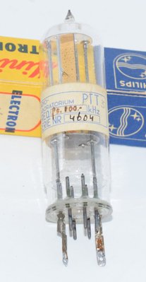
Introduction and History
The RCA 4604 is a quick-heating beam power tube designed primarily as an RF power amplifier for push-pull service in mobile and emergency communications equipment. Manufactured by the Electron Tube Division of the Radio Corporation of America (RCA) in Harrison, New Jersey, the 4604 was introduced around 1960 (the datasheet is dated 10-60) to serve the growing demands of mobile radio, FM telephony, and Class C telegraphy applications.
The 4604 was engineered to address a specific need in the communications industry: a compact, rugged, high-sensitivity power tube that could deliver substantial RF output while reaching operating temperature almost instantly. With its oxide-coated filament reaching operating temperature in less than one second after filament voltage is applied, the 4604 was ideally suited for push-to-talk mobile and emergency communications systems where instant-on capability was essential.
The tube features a rugged button-stem construction with short internal leads, triple base-pin connections for grid No.3 and filament, and an internal shield joined to the base sleeve inside the tube. This internal shielding, combined with the metal base sleeve, provided complete isolation between input and output circuits — a critical requirement for stable RF amplifier operation at frequencies up to 175 Mc. The plate lead exits through a top cap opposite the base, further ensuring separation of input and output circuits.
While designed primarily for RF service, the 4604's high transconductance, beam power architecture, and robust construction have attracted interest from experimenters and audio enthusiasts exploring unconventional tube choices for audio amplification.
Technical Specifications and Design
Filament (Heater) Ratings
| Parameter | Value |
|---|---|
| Filament Voltage (AC or DC) | 6.3 ± 10% volts |
| Filament Current at 6.3 volts | 0.65 ampere |
| Filament Current Range (at 6.3V AC) | 0.59 min. – 0.71 max. ampere |
| Heating Time | 1 second |
| Filament Type | Coated, oxide-coated, quick-heating |
Key Electrical Characteristics
| Parameter | Conditions | Value |
|---|---|---|
| Transconductance (gm) | Plate volts = 200, Grid No.2 volts = 200, Plate mA = 100 | 6000 µmhos |
| Mu-Factor (µ), Grid No.2 to Grid No.1 | Plate volts = 200, Grid No.2 volts = 200, Plate mA = 100 | 4 |
Note: The plate resistance (rp) is not explicitly stated in the RCA datasheet. It can be estimated from the relationship rp = µ/gm. Using the mu-factor of Grid No.2 to Grid No.1 (µ = 4) and gm = 6000 µmhos, this yields approximately 667 ohms, though this value should be confirmed against additional manufacturer data as the mu-factor given is specifically the Grid No.2 to Grid No.1 mu-factor, not the conventional amplification factor.
Direct Interelectrode Capacitances
| Capacitance | Value |
|---|---|
| Grid No.1 to Plate | 0.24 max. µµf |
| Grid No.1 to Filament & Grid No.3 & Internal Shield, Base Sleeve and Grid No.2 | 11 µµf |
| Plate to Filament & Grid No.3 & Internal Shield, Base Sleeve and Grid No.2 | 8.5 µµf |
Characteristics Range Values for Equipment Design
| Parameter | Min. | Max. |
|---|---|---|
| Direct Interelectrode Capacitance: Grid No.1 to Plate | — | 0.24 µµf |
| Grid No.1 to Filament & Grid No.3 & Internal Shield, Base Sleeve and Grid No.2 | 9.5 | 12.5 µµf |
| Plate to Filament & Grid No.3 & Internal Shield, Base Sleeve and Grid No.2 | 7.3 | 9.5 µµf |
| Plate Current | 46 | 94 mA |
| Grid No.2 Current | — | 5.5 mA |
| Useful Power Output | 47 | — watts |
Maximum ICAS Ratings — RF Power Amplifier & Oscillator (Class C Telegraphy and Class C FM Telephony)
Absolute-Maximum Values, up to 60 Mc:
| Parameter | Value |
|---|---|
| DC Plate Voltage | 750 max. volts |
| DC Grid No.2 Voltage | 250 max. volts |
| DC Grid No.1 Voltage | -150 max. volts |
| DC Plate Current | 150 max. mA |
| DC Grid No.1 Current | 4 max. mA |
| Plate Input | 90 max. watts |
| Grid No.2 Input | 3 max. watts |
| Plate Dissipation | 25 max. watts |
Typical Operation as Amplifier at 175 Mc
| Parameter | Value |
|---|---|
| DC Plate Voltage | 400 volts |
| DC Grid No.2 Voltage | 190 volts |
| Grid No.2 Series Resistor | 18000 ohms |
| DC Grid No.1 Voltage | -60 volts |
| Grid No.1 Resistor | 30000 ohms |
| DC Plate Current | 150 mA |
| DC Grid No.2 Current | 11 mA |
| DC Grid No.1 Current (Approx.) | 2 mA |
| Driving Power (Approx.) | 4.5 watts |
| Power Output (Approx.) | 30 watts |
Maximum Circuit Values
| Parameter | Value |
|---|---|
| Grid No.1 Circuit Resistance | 30000 max. ohms |
Power Ratings by Frequency
- Up to 60 Mc: 90 watts CW input (ICAS)
- At 175 Mc: 60 watts CW input (ICAS)
Physical Construction
| Parameter | Value |
|---|---|
| Bulb Type | T-12 |
| Cap | Small (JEDEC No. C1-1) |
| Base | Small Wafer Octal 8-Pin with Sleeve (JEDEC Group 1, No. B8-150) |
| Maximum Overall Length | 3-13/16" |
| Seated Length | 3-1/8" ± 1/8" |
| Maximum Diameter | 1-21/32" |
| Operating Position | Vertical, or horizontal with plane of pins 3 and 7 vertical |
| Bulb Temperature (at hottest point) | 220 max. °C |
Pin Configuration (Bottom View, JEDEC 7CL Designation)
| Pin | Connection |
|---|---|
| Pin 1 | Filament Tap, Grid No.3, Internal Shield |
| Pin 2 | Filament |
| Pin 3 | Grid No.2 (Screen Grid) |
| Pin 4 | Same as Pin 1 (Filament Tap, Grid No.3, Internal Shield) |
| Pin 5 | Grid No.1 (Control Grid) |
| Pin 6 | Same as Pin 1 (Filament Tap, Grid No.3, Internal Shield) |
| Pin 7 | Filament |
| Pin 8 | Base Sleeve (BC) |
| Cap (Top) | Plate |
The triple base-pin connections for Grid No.3, filament tap, and internal shield (pins 1, 4, and 6) provide effective RF grounding. The base sleeve (pin 8) has its own dedicated connection. The plate connection is brought out through the top cap to maintain maximum isolation from the input circuit at the base.
Applications and Usage
Primary Designed Applications
The RCA 4604 was specifically designed for the following services:
- Push-Pull RF Power Amplifier: The primary intended application, in mobile and emergency communications equipment operating in Class C telegraphy and Class C FM telephony modes.
- RF Oscillator: Capable of serving as a self-excited oscillator in single-tube configurations, with a dc plate voltage of 600 volts, grid No.2 voltage of 200 volts, grid No.1 resistor of 30000 ± 10% ohms, plate current of 100 to 112 mA, and grid No.1 current of 2 to 2.5 mA at 15 Mc.
- Mobile Radio: The quick-heating filament (1 second) made it ideal for push-to-talk mobile radio systems where the tube needed to be operational almost immediately.
- Emergency Communications: The rugged construction and reliable quick-start capability suited emergency and field communications equipment.
Push-Pull and Parallel Operation
Two 4604s in parallel or push-pull will deliver approximately twice the power output of a single tube. The parallel connection requires no increase in excitation voltage to drive a single tube. The push-pull arrangement offers the advantage of simplifying the balancing of high-frequency circuits. When two 4604s are used in push-pull or parallel with filaments connected in series across a 12.6-volt supply, a different bias voltage is required for each tube, and the relative polarity of the filament terminals must be maintained when switching between negative-ground and positive-ground supplies.
Frequency Range
The 4604 is rated for full input power (90 watts CW, ICAS) up to 60 Mc, with reduced input (60 watts CW, ICAS) at 175 Mc. The datasheet includes a graph (Fig. 4) showing maximum ratings versus operating frequency for ICAS Class C telegraphy or telephony service, with plate input voltage declining from approximately 800 volts at low frequencies to around 400 volts at 200 Mc.
Operational Considerations
The datasheet provides several important operational notes:
- The plate shows no color when the 4604 is operated at full ratings under ICAS conditions — this is a key indicator of proper operation.
- Grid No.2 voltage should be obtained from a source of good regulation. The plate voltage should be applied before or simultaneously with the grid No.2 voltage to prevent excessive screen dissipation.
- Grid No.2 current is a very sensitive indication of plate-circuit loading. Current rises excessively (potentially damaging the tube) when the amplifier is operated without load.
- When tuning a 4604 under no-load conditions, care must be taken to prevent exceeding the grid No.2 input rating.
- Heavy leads and conductors with suitable insulation should be used in all parts of the RF plate circuit to minimize losses. Short, heavy leads are essential at higher frequencies to minimize lead inductance.
- A 2500-ohm protective resistor in the high-voltage supply lead is recommended when operated at maximum ratings with a series dropping resistor for screen voltage. A 10000-ohm protective resistor is recommended when a separate grid No.2 voltage supply is used.
- Grid No.2 voltage must not exceed 400 volts under key-up conditions.
- Free circulation of air must be provided around the 4604, as the bulb becomes hot during operation.
Sound Characteristics
The RCA 4604 was not designed as an audio tube, and there is very limited documented experience with it in audio amplifier circuits. However, based on its electrical characteristics and the general behavior of beam power tubes with similar parameters, some observations can be made:
- High Transconductance Character: With a transconductance of 6000 µmhos, the 4604 is a highly sensitive tube. In audio applications, high-gm beam power tubes tend to produce a lively, dynamic sound with strong transient response. The tube would require very little drive voltage to produce significant output.
- Beam Power Tonality: As a beam power tube, the 4604 would be expected to produce the characteristic beam tetrode sound — tighter and more controlled bass response compared to true pentodes, with a somewhat more linear midrange. The beam-forming plates help reduce screen current and improve efficiency, which in audio terms often translates to a cleaner, more authoritative presentation.
- Quick-Heating Filament Considerations: The oxide-coated, quick-heating filament is designed for rapid warm-up rather than for the thermal stability prized in audio applications. This could potentially introduce slightly more microphonic behavior compared to tubes designed specifically for audio service, though the rugged button-stem construction would help mitigate this.
- RF Design Heritage: Tubes designed for RF service often have very low grid-to-plate capacitance (0.24 µµf max. for the 4604), which in audio applications means excellent stability and minimal Miller effect. This can translate to extended high-frequency response and a sense of openness in the treble.
- Potential Brightness: The combination of high transconductance and low interelectrode capacitances may give the 4604 a somewhat bright or forward character in audio circuits, particularly in the upper midrange and treble regions. This is speculative and would depend heavily on the circuit topology and operating point chosen.
It must be emphasized that these sound characteristics are largely theoretical extrapolations. The 4604 has not established a reputation in the audio community, and anyone considering it for audio use would be venturing into experimental territory.
Equivalent or Substitute Types
The RCA 4604 is a specialized beam power tube with a somewhat unique combination of characteristics. Direct equivalents are not widely documented. Some considerations:
- No direct, drop-in equivalent has been identified in standard tube substitution guides for the 4604. Its combination of quick-heating filament, top-cap plate connection, internal shielding, base sleeve, and specific operating parameters make it a distinctive type.
- The tube shares some general characteristics with other beam power tubes designed for mobile communications RF service from the same era, but pin-for-pin substitution should not be assumed without careful verification of all electrical and mechanical parameters.
- The PTT Serie NR 4064 from Radion Laboratorium has been noted as a related product — described as a very unusual old frequency valve — but the exact nature of its relationship to the RCA 4604 (whether equivalent, predecessor, or merely similar in application) should be confirmed against manufacturer documentation.
Caution: Given the high voltages involved (up to 750V plate, 250V screen) and the specific circuit requirements of the 4604, substitution with any other tube type should only be attempted after thorough analysis of all electrical ratings, pin connections, and mechanical compatibility. The internal shield and base sleeve connections are particularly important for proper RF operation and may not be replicated in substitute types.
Notable Characteristics
Quick-Heating Filament
Perhaps the most distinctive feature of the 4604 is its oxide-coated filament that reaches operating temperature in less than one second. This was a critical feature for push-to-talk mobile radio systems where the transmitter tube needed to be ready almost instantly when the operator keyed the microphone. The filament draws 0.65 amperes at 6.3 volts.
Exceptional Input-Output Isolation
The 4604 achieves remarkable isolation between input and output circuits through multiple design features:
- Grid-to-plate capacitance of only 0.24 µµf maximum
- Internal shield connected to the base sleeve
- Plate connection brought out through the top cap, physically opposite the base
- Triple base-pin connections (pins 1, 4, and 6) for grid No.3, filament tap, and internal shield, providing effective RF grounding
- Metal base sleeve with its own dedicated pin (pin 8)
Rugged Construction
The button-stem construction with short internal leads provides mechanical ruggedness suitable for mobile installations subject to vibration and shock. The T-12 bulb envelope is compact yet provides adequate heat dissipation for 25 watts of plate dissipation.
High Power Sensitivity
With a transconductance of 6000 µmhos, the 4604 offers high power sensitivity — meaning it can deliver substantial output power with relatively modest driving power. At 175 Mc, approximately 4.5 watts of driving power yields about 30 watts of output power, demonstrating a power gain of roughly 6.7 (8.3 dB).
Versatile Frequency Range
The tube operates effectively from low frequencies up to 175 Mc (and beyond with reduced ratings), covering the VHF communications bands that were rapidly expanding in the late 1950s and early 1960s.
Thermal Considerations
The bulb temperature can reach 220°C at the hottest point. Adequate cooling with free air circulation is essential. The plate should show no color when operated at full ICAS ratings — any visible glow indicates excessive dissipation.
Usage in the Audio Community
The RCA 4604 occupies an extremely niche position in the audio world. It was never intended for audio service, and its adoption by the audio community has been minimal at best. However, several factors make it an interesting candidate for adventurous audio experimenters:
Potential Audio Applications
- Single-Ended (SE) Amplifiers: With 25 watts of plate dissipation and high transconductance, the 4604 could theoretically deliver several watts in a single-ended Class A audio amplifier configuration. The top-cap plate connection adds complexity but also provides excellent isolation that could benefit audio circuit layout.
- Push-Pull Audio Amplifiers: Given that the tube was designed for push-pull RF service, a push-pull audio amplifier using a pair of 4604s could potentially deliver meaningful audio power. The high transconductance means the driver stage requirements would be modest.
- Experimental Projects: The 4604 appeals to the subset of audio enthusiasts who enjoy building amplifiers around unusual or repurposed tubes. The challenge of adapting an RF power tube for audio service — designing appropriate output transformers, establishing proper bias points for linear audio operation, and managing the top-cap plate connection — is part of the appeal for these builders.
Challenges for Audio Use
- Top-Cap Plate Connection: The plate exits through a top cap, which complicates chassis layout for audio amplifiers and requires careful insulation given the high voltages involved.
- Filament Configuration: The filament center-tap is internally connected to grid No.3 and the internal shield (pins 1, 4, 6). This fixed internal connection limits flexibility in grounding and biasing arrangements compared to tubes where these connections are brought out separately.
- No Audio Operating Data: RCA published no audio operating conditions for the 4604. Anyone using it for audio must derive their own operating points from the characteristic curves provided in the datasheet (Figs. 1, 2, and 3), which show plate characteristics at various grid voltages with grid No.2 at 200 volts.
- Availability: The 4604 is not a common tube on the surplus market. Finding matched pairs for push-pull service may be difficult.
- Output Transformer: No commercially available audio output transformers are designed for the 4604's specific impedance requirements. Custom or adapted transformers would be necessary.
- Lack of Community Knowledge: Unlike popular audio tubes (6L6, EL34, 6550, KT88, etc.), there is virtually no community-shared knowledge about the 4604's behavior in audio circuits. Builders would be largely on their own.
Appeal to Collectors
The RCA 4604 is of interest to tube collectors as a representative of the specialized mobile communications tubes of the late 1950s and early 1960s. Its compact size, distinctive top-cap construction, and RCA branding make it an attractive display piece. The tube's relative obscurity adds to its collectibility among enthusiasts who specialize in unusual or uncommon types.
Practical Recommendation
For anyone seriously considering the 4604 for audio use, the characteristic curves on page 3 of the datasheet provide the necessary data to establish a Class A operating point. A reasonable starting point for experimentation might be a plate voltage of 200-300 volts, screen voltage of 200 volts, and a bias voltage chosen from the curves to place the operating point in the linear region. However, this is entirely experimental territory, and builders should proceed with appropriate caution given the voltages involved and the lack of established audio circuit designs for this tube type.