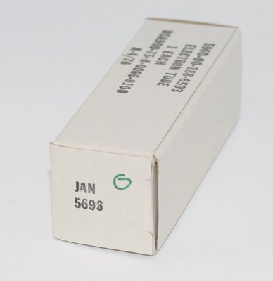
Introduction and History
The 5696 is a miniature type gas-tetrode thyratron designed for use in counter-circuit relay applications. Manufactured by RCA and other producers under the Joint Army-Navy (JAN) specification system, the 5696 was developed during the post-World War II era when the electronics industry was transitioning from octal-based industrial tubes to more compact miniature envelope designs. The tube was part of a family of gas thyratrons that included the larger octal-based 2050/2050A and the related 5727 "Premium" type.
Gas thyratrons like the 5696 represented an important class of switching devices before the advent of solid-state thyristors (SCRs). They were widely used in industrial control systems, counting circuits, timing circuits, and relay-replacement applications throughout the 1950s and 1960s. The 5696 offered the advantages of miniaturization — using the compact 7-pin miniature base — while maintaining the robust switching characteristics required for industrial service.
RCA classified the 5696 as an "Industrial Type," indicating it was built to tighter tolerances and more demanding environmental specifications than standard consumer-grade receiving tubes. JAN (Joint Army-Navy) versions, such as the 5696 JAN RCA, were manufactured to military specifications ensuring consistent quality and reliability across production lots.
Technical Specifications and Design
General Description
The 5696 is a miniature type gas-tetrode thyratron designed for use in counter-circuit relay applications. It uses a miniature glass envelope and requires a miniature 7-contact socket.
Heater Ratings
| Parameter | Value |
|---|---|
| Heater Voltage (ac/dc) | 6.3 volts |
| Heater Current | 0.150 ampere |
| Heater-Cathode Voltage (Peak) | +25, −100 volts |
Cathode
| Parameter | Value |
|---|---|
| Minimum Heating Time, prior to tube conduction | 10 seconds |
Direct Interelectrode Capacitances (Approx.)
| Parameter | Value |
|---|---|
| Grid No. 1 to Anode | 0.03 pF |
| Input | 1.8 pF |
| Output | 0.54 pF |
Ionization Time (Approx.)
| Conditions | Value |
|---|---|
| DC anode volts = 100, grid-No.1 square-pulse volts = +50, peak cathode amperes during conduction = 0.150 | 0.5 μs |
Deionization Time (Approx.)
| Conditions | Value |
|---|---|
| DC anode volts = 500, grid-No.1 volts = −100, grid-No.1 resistor (ohms) = 1000, dc cathode amperes = 0.025 | 25 μs |
| DC anode volts = 500, grid-No.1 volts = −13, grid-No.1 resistor (ohms) = 1000, dc cathode amperes = 0.025 | 40 μs |
Other Characteristics
| Parameter | Value |
|---|---|
| Maximum Critical Grid-No.1 Current, with ac anode-supply volts (rms) = 350, and average cathode amperes = 0.025 | 0.5 μA |
| Anode Voltage Drop (Approx.) | 10 volts |
| Grid-No.1 Control Ratio (Approx.) with grid-No.1 resistor (megohms) = 0, grid-No.2 volts = 0 | 250 |
| Grid-No.2 Control Ratio (Approx.) with grid-No.1 volts = 0, grid-No.2 resistor (ohms) = 0 | 15 |
Relay and Grid-Controlled Rectifier Service — Maximum Ratings (Absolute-Maximum Values)
| Parameter | Value |
|---|---|
| Peak Anode Voltage — Forward | 500 volts |
| Peak Anode Voltage — Inverse | 500 volts |
| Grid-No.2 (Shield-Grid) Voltage — Peak, before anode conduction | −50 volts |
| Grid-No.2 (Shield-Grid) Voltage — Average, during anode conduction | −10 volts |
| Grid-No.1 (Control-Grid) Voltage — Peak, before anode conduction | −100 volts |
| Grid-No.1 (Control-Grid) Voltage — Average, during anode conduction | −10 volts |
| Cathode Current — Peak | 100 mA |
| Cathode Current — Average* | 25 mA |
| Cathode Current — Surge, for duration of 0.1 sec. max. | 2 amperes |
| Grid-No.2 Current — Average* | 5 mA |
| Grid-No.1 Current — Average* | 5 mA |
| Ambient Temperature Range | −55 to +90 °C |
* Averaged over any interval of 30 seconds maximum.
Typical Operating Conditions for Relay Service
| Parameter | Value |
|---|---|
| RMS Anode Voltage | 117 volts |
| Grid No. 2 | Connected to cathode at socket |
| RMS Grid-No.1 Bias Voltage (approx. 180° out of phase with anode voltage) | 5 volts |
| Peak Grid-No.1 Signal Voltage | 5 volts |
| Grid-No.1-Circuit Resistance | 0.1 megohm |
| Anode-Circuit Resistance | 5000 ohms |
Maximum Circuit Value
| Parameter | Value |
|---|---|
| Grid-No.1-Circuit Resistance | 10 megohms |
Physical Details
| Parameter | Detail |
|---|---|
| Envelope | Miniature glass (T-5½) |
| Base | Miniature 7-pin (B7G / 7BN) |
| Mounting Position | Any |
| Classification | Industrial Type |
Pin Configuration (7BN Base)
| Pin | Connection |
|---|---|
| Pin 1 | Grid No. 1 (Control Grid, G1) |
| Pin 2 | Cathode (K) |
| Pin 3 | Heater (H) |
| Pin 4 | Heater (H) |
| Pin 5 | Grid No. 2 (Shield Grid, G2) |
| Pin 6 | Plate / Anode (P) |
| Pin 7 | Grid No. 2 (G2) |
Note: As a gas thyratron, the 5696 does not have conventional amplification factor (μ), transconductance (gm), or plate resistance (rp) specifications in the way that vacuum-type amplifying tubes do. Instead, its key parameters are the control ratio, ionization time, deionization time, anode voltage drop, and critical grid current — all of which are specified above from the manufacturer datasheet. The control ratio serves an analogous function to the amplification factor, describing the relationship between grid voltage and the anode voltage at which the tube fires.
Applications and Usage
The 5696 was designed primarily for the following applications:
Counter Circuits
The 5696's primary intended application was in electronic counting circuits (scalers). Its fast ionization time of approximately 0.5 μs and deionization times of 25–40 μs (depending on circuit conditions) made it suitable for moderate-speed counting applications. Ring counters and decade counters using banks of thyratrons were common in nuclear instrumentation, industrial process control, and early computing equipment.
Relay Service
The tube could replace electromechanical relays in applications requiring fast, silent, and wear-free switching. With typical relay service operating at 117 V RMS anode voltage and the shield grid connected to the cathode, the 5696 provided reliable on/off control with no moving parts. The anode-circuit resistance of 5000 ohms in typical relay service limited the current to safe levels.
Grid-Controlled Rectifier Service
Like other gas thyratrons, the 5696 could function as a grid-controlled rectifier, allowing precise control of the conduction angle in AC circuits. This made it useful for motor speed control, lamp dimming, and other power control applications within its current ratings.
Timing Circuits
The predictable firing characteristics and control ratios (Grid-No.1 control ratio of approximately 250, Grid-No.2 control ratio of approximately 15) made the 5696 useful in timing and sequencing circuits where a precise trigger threshold was required.
Industrial Control
The wide ambient temperature range of −55 to +90°C and the JAN military qualification made the 5696 suitable for harsh industrial and military environments where reliability was paramount.
Operating Considerations
The heater must be allowed to reach normal operating temperature before anode current is drawn. The delay period should not be less than 10 seconds after application of heater voltage. Failure to observe this warm-up requirement will result in cathode damage. The heater is designed to operate on either AC or DC at 6.3 volts, and the heater voltage must never be allowed to deviate from its rated range.
Sufficient anode-circuit resistance, including the tube load, must be used under any conditions of operation to prevent exceeding the current ratings of the tube. The maximum grid-No.1 circuit resistance of 10 megohms allows for very high-impedance trigger circuits, giving the 5696 excellent sensitivity for detecting small control signals.
Sound Characteristics
It is important to note that the 5696 is a gas thyratron — a switching device — and not a linear amplifying tube. As such, it does not have "sound characteristics" in the traditional audiophile sense of how a tube colors or shapes an audio signal in a linear amplification circuit. The 5696 operates as a bistable device: it is either non-conducting or fully conducting, with an anode voltage drop of approximately 10 volts during conduction.
However, in certain creative and experimental audio contexts, gas thyratrons including the 5696 have been explored for their unique sonic properties:
- Harsh, aggressive clipping: When misused or creatively employed in audio signal paths, thyratrons produce extremely hard clipping due to their binary on/off conduction behavior. This creates a distinctive, buzzy, aggressive distortion character quite unlike the soft clipping associated with vacuum triodes or pentodes.
- Relaxation oscillator tones: The 5696 can be configured in sawtooth relaxation oscillator circuits, producing raw, buzzy waveforms with rich harmonic content. These tones have a characteristic "retro-electronic" quality reminiscent of early electronic music instruments.
- Glow and visual appeal: Like all gas thyratrons, the 5696 produces a visible ionization glow (typically purple or blue-violet) when conducting. While not a "sound" characteristic per se, this visual element adds to the aesthetic appeal in experimental audio setups and art installations.
The 5696 should not be compared to audio amplifying tubes such as the 12AX7, 12AU7, 6L6, or EL34 in terms of tonal quality. Its design purpose is fundamentally different, and any audio application represents a creative departure from the tube's intended use.
Equivalent or Substitute Types
| Type | Relationship | Notes |
|---|---|---|
| CV3512 | Close/identical substitute | British military (CV) designation for the same tube. Direct drop-in replacement with identical specifications and pinout. |
| 5696A | Different rating substitute — NOT a direct drop-in | An improved or differently-rated version of the 5696. While sharing the same base type and general construction, the 5696A may have different maximum ratings or tighter tolerances. Circuit designers should verify that the specific ratings of the 5696A are compatible with their application before substituting. |
The 5696 is related to but not interchangeable with the following types:
- 5727: A miniature "Premium" gas-tetrode thyratron also using the 7BN base, but with significantly different ratings. The 5727 has a heater current of 0.6 ampere (vs. 0.150 A for the 5696), higher peak anode voltage ratings (650 V forward, 1300 V inverse for relay service), and higher current capability (0.5 A peak, 0.1 A average cathode current). The 5727 is NOT a substitute for the 5696.
- 2050/2050A: Octal-based gas thyratrons with similar function but entirely different physical format (6BS octal base) and much higher current ratings. Not interchangeable.
Notable Characteristics
- Extremely low heater power consumption: At 6.3 V and only 0.150 A, the 5696 consumes less than 1 watt of heater power — remarkably economical for a thyratron. This made it ideal for battery-operated or portable equipment and for circuits using many thyratrons in parallel (such as multi-decade counters).
- Very low interelectrode capacitances: The grid-to-anode capacitance of only 0.03 pF is exceptionally low, minimizing unwanted coupling between the trigger circuit and the anode circuit. This contributes to clean, predictable firing behavior.
- Fast ionization time: The 0.5 μs ionization time allows the 5696 to respond rapidly to trigger pulses, making it suitable for counting applications at moderate repetition rates.
- High grid-circuit resistance tolerance: The maximum grid-No.1 circuit resistance of 10 megohms allows the tube to be triggered by very high-impedance sources, providing excellent sensitivity.
- Wide temperature range: The −55 to +90°C ambient temperature specification reflects the tube's industrial/military heritage and ensures reliable operation in demanding environments.
- Dual control grids: The tetrode structure with both a control grid (G1) and a shield grid (G2) provides design flexibility. The shield grid can be connected to the cathode for standard operation, or biased independently to shift the control characteristic of Grid No. 1, effectively providing two independent control inputs.
- Low anode voltage drop: The approximately 10-volt anode drop during conduction is typical for gas thyratrons and means that most of the supply voltage appears across the load, contributing to efficient power transfer in switching applications.
- Compact miniature construction: The 7-pin miniature (B7G) base allowed the 5696 to be used in much more compact equipment than was possible with octal-based thyratrons like the 2050A, an important consideration in the increasingly miniaturized electronics of the 1950s and 1960s.
Usage in the Audio Community
The 5696 occupies a niche position in the audio community, far removed from mainstream tube audio applications. Its use is almost exclusively confined to experimental, avant-garde, and electronic music contexts:
Experimental Synthesizer Circuits
The most common audio-related application for the 5696 is in DIY and experimental synthesizer oscillator circuits. Thyratron relaxation oscillators produce sawtooth waveforms that can be used as audio oscillators or low-frequency oscillators (LFOs). The 5696's low power consumption makes it practical for inclusion in modular synthesizer systems. Builders of "lunetta" style and other experimental noise synthesizers sometimes incorporate the 5696 for its unique waveform generation capabilities and the visual appeal of its gas discharge glow.
Sound Art and Installations
Artists working at the intersection of sound and visual art have used gas thyratrons including the 5696 in installations where the visible ionization glow is synchronized with or responsive to audio signals. The tube's dramatic visual discharge adds a performative element that purely solid-state circuits cannot replicate.
Guitar Effect Pedals (Rare/Experimental)
A very small number of boutique and experimental guitar effect pedal builders have experimented with thyratrons for extreme distortion effects. The 5696's hard switching behavior produces a type of distortion that is fundamentally different from conventional tube overdrive — more akin to a gated fuzz with an aggressive, sputtering character. These applications are extremely rare and represent creative experimentation rather than established practice.
Collector and NOS Market
The 5696 appears in the NOS (New Old Stock) tube market, primarily sold to experimenters, collectors, and synthesizer builders. JAN-spec RCA examples are the most commonly encountered and are generally available at modest prices, as demand is limited compared to popular audio tubes. The tube's industrial heritage means that surviving NOS stock is typically of high quality, having been manufactured to military specifications.
Practical Considerations for Audio Experimenters
Those considering the 5696 for audio experimentation should be aware of several important factors:
- The 10-second minimum warm-up time must be observed before any anode voltage is applied to prevent cathode damage.
- Adequate current-limiting resistance must always be present in the anode circuit — the tube will conduct heavily without it, potentially destroying itself and other circuit components.
- The gas fill means the tube has a finite life that is affected by operating conditions; excessive current or improper warm-up will significantly shorten tube life.
- The 5696 is not a linear amplifier and cannot be used as a drop-in replacement for any audio amplifying tube.
- High-voltage safety precautions must be observed, as the tube can operate with anode voltages up to 500 volts peak.
In summary, while the 5696 is not an audio tube in the conventional sense, it has found a small but dedicated following among experimental musicians, sound artists, and synthesizer builders who value its unique switching characteristics, distinctive gas-discharge glow, and the raw, aggressive sonic textures it can produce in creative circuit configurations.