Introduction and History
The 6146 is a beam power pentode (sometimes classified as a beam tetrode in certain literature) designed primarily for use as an RF power amplifier, AF power amplifier, and modulator. Introduced by RCA in the early 1950s, the 6146 quickly became one of the most popular and versatile transmitting tubes ever manufactured. Its combination of moderate power capability, compact size, and excellent RF performance made it a staple in amateur radio transmitters, military communications equipment, and commercial broadcast gear throughout the 1950s, 1960s, and beyond.
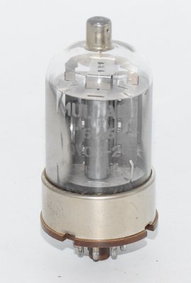
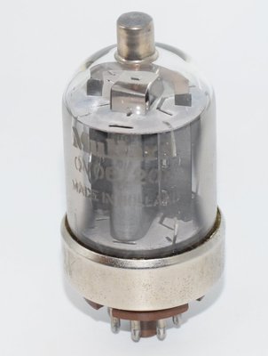
The tube was manufactured by virtually every major valve producer worldwide, including RCA, GE, Sylvania, Tung-Sol, Amperex, Mullard, Philips, and the French manufacturer CIFTE (under the Mazda-Belvu brand). The Mullard/Philips designation for this tube was QV06/20E. The 6146 saw extensive military use and was assigned multiple CV (Common Valve) numbers including CV3523 and CV8218.
The 6146 was later followed by improved versions — the 6146A and 6146B — which offered enhanced stability under reduced heater voltage conditions and tighter specifications, though these are not direct drop-in replacements in all circuits due to rating differences. The original 6146 remains highly sought after by amateur radio operators, vintage equipment restorers, and increasingly by the audio community for its distinctive sonic characteristics.
The tube uses an indirectly heated cathode with a parallel filament arrangement, housed in a T12-18bis glass envelope with an 8-pin octal base (8C 18-10) and a top cap (C 9-1) for the anode connection. This top-cap anode design provides excellent isolation between input and output circuits, which is critical for stable RF operation at VHF frequencies.
Technical Specifications and Design
Heater / Filament
| Parameter | Value |
|---|---|
| Heater Voltage (Vf) | 6.3 V |
| Heater Current (If) | 1.25 A |
| Heater Type | Indirectly heated cathode, parallel filament |
Maximum Ratings (Absolute Maximum System — Amateur/Commercial Intermittent, T.A.C.I.)
| Parameter | T.C.C. (Continuous) | T.A.C.I. (Intermittent) |
|---|---|---|
| Maximum Anode Voltage (Va) | 600 V | 750 V max |
| Maximum Screen Grid Voltage (Vg2) | 250 V | 250 V max |
| Maximum Anode Current (Ia) | 125 mA | 135 mA max |
| Maximum Plate Dissipation (Pa) | 20 W | 25 W max |
| Maximum Plate Dissipation — ICAS (PaN) | 60 W | 85 W max |
| Maximum Screen Grid Dissipation (Pg2) | 3 W | 3 W max |
| Maximum Peak Filament-to-Cathode Voltage (Vfk) | 135 V | 135 V max |
| Maximum Bulb Temperature | 220°C | 220°C max |
Nominal Characteristics (at Va = 200 V, Vg2 = 200 V)
| Parameter | Value |
|---|---|
| Anode Current (Ia) | 100 mA |
| Transconductance (S / gm) | 7 mA/V |
Interelectrode Capacitances (without external shielding)
| Parameter | Symbol | Value |
|---|---|---|
| Grid No. 1 to Anode (feedback capacitance) | Cg1/a (Cga) | 0.24 pF max |
| Input Capacitance | Ce (Cgk) | 13.5 pF max |
| Output Capacitance | Cs (Cak) | 8.5 pF max |
Note: The verified reference data lists Cgk as 13 pF while the Mazda-Belvu datasheet specifies Ce as 13.5 pF max. This minor discrepancy likely reflects measurement conditions; the 13.5 pF figure includes stray capacitance contributions. Both values are within normal tolerance.
Physical Construction
| Parameter | Value |
|---|---|
| Envelope | T12-18bis glass |
| Base | Octal (8C 18-10) |
| Anode Connection | Top cap (C 9-1) |
| Maximum Diameter | 39.7 mm max |
| Maximum Seated Height | 82.5 mm max |
| Maximum Overall Height | 96.8 mm max |
Pin Configuration (Octal Base — Bottom View)
| Pin | Connection |
|---|---|
| Pin 1 | Cathode, Grid No. 3 (suppressor), Internal shield |
| Pin 2 | Filament (heater) |
| Pin 3 | Grid No. 2 (screen) |
| Pin 4 | Cathode, Grid No. 3, Internal shield (internal connection) |
| Pin 5 | Grid No. 1 (control grid) |
| Pin 6 | Cathode, Grid No. 3, Internal shield (internal connection) |
| Pin 7 | Filament (heater) |
| Pin 8 | Metal shell of base (external shield) |
| Top Cap | Anode (plate) |
Important Note: Pins 4 and 6 are internal connections to the cathode/suppressor/internal shield structure. They must not be used as external tie points for other circuit connections, though they are internally connected to pin 1.
Typical Operating Conditions — Class AB1 AF Amplifier and Modulator (values per pair of tubes)
| Parameter | Va=400V | Va=500V | Va=600V |
|---|---|---|---|
| Screen Voltage (Vg2) | 190 V | 185 V | 180 V |
| Control Grid Voltage (Vg1) | -40 V | -40 V | -45 V |
| Peak Input Voltage (2 Ve cr) | 80 V | 80 V | 90 V |
| Zero-Signal Plate Current (Ia sig 0) | 63 mA | 57 mA | 26 mA |
| Max-Signal Plate Current (Ia sig max) | 228 mA | 215 mA | 200 mA |
| Anode Load Resistance (R aa) | 4 kΩ | 5.5 kΩ | 7 kΩ |
| Max Signal Output Power (Ps sig max) | 55 W | 70 W | 82 W |
Typical Operating Conditions — Triode Connection, Class AB1 (values per pair of tubes)
| Parameter | Va=250V | Va=400V | Va=400V (T.A.C.I.) |
|---|---|---|---|
| Control Grid Voltage (Vg1) | -50 V | -100 V | -100 V |
| Peak Input Voltage (2 Ve cr) | 100 V | 200 V | 200 V |
| Zero-Signal Plate Current (Ia sig 0) | 120 mA | 40 mA | 40 mA |
| Max-Signal Plate Current (Ia sig max) | 125 mA | 100 mA | 100 mA |
| Anode Load Resistance (R aa) | 5 kΩ | 8 kΩ | 8 kΩ |
| Max Signal Output Power (Ps sig max) | 10 W | 22 W | 22 W |
Typical Operating Conditions — Class C RF Amplifier (Telegraphy, CW, per tube)
| Parameter | Condition 1 | Condition 2 | Condition 3 |
|---|---|---|---|
| Anode Voltage (Va) | 500 V | 600 V | 750 V |
| Screen Voltage (Vg2) | 170 V | 150 V | 160 V |
| Control Grid Voltage (Vg1) | -66 V | -58 V | -62 V |
| Anode Current (Ia) | 135 mA | 112 mA | 120 mA |
| Screen Current (Ig2) | 9 mA | 9 mA | 11 mA |
| Output Power (Ps) | 48 W | 52 W | 70 W |
Typical Operating Conditions — Class C RF Amplifier (Telephony/AM, per tube)
| Parameter | Condition 1 | Condition 2 |
|---|---|---|
| Anode Voltage (Va) | 400 V | 600 V |
| Screen Voltage (Vg2) | 150 V | 150 V |
| Control Grid Voltage (Vg1) | -87 V | -87 V |
| Anode Current (Ia) | 112 mA | 112 mA |
| Screen Current (Ig2) | 7.8 mA | 7.8 mA |
| Output Power (Ps) | 32 W | 52 W |
Typical Operating Conditions — Class AB2 RF/AF Amplifier (per pair of tubes)
| Parameter | Va=600V | Va=750V |
|---|---|---|
| Screen Voltage (Vg2) | 190 V | 165 V |
| Control Grid Voltage (Vg1) | -48 V | -46 V |
| Anode Current (Ia) — zero to max signal | 28–270 mA | 22–240 mA |
| Screen Current (Ig2) — zero to max signal | 1.2–20 mA | 0.3–20 mA |
| Output Power (Ps sig max) | 113 W | 131 W |
| Total Distortion | 11% | 10% |
Typical Operating Conditions — Class AB1 (per pair of tubes, T.A.C.I.)
| Parameter | Va=750V |
|---|---|
| Screen Voltage (Vg2) | 195 V |
| Control Grid Voltage (Vg1) | -50 V |
| Anode Current (Ia) — zero to max signal | 23–220 mA |
| Screen Current (Ig2) — zero to max signal | 1–26 mA |
| Output Power (Ps sig max) | 120 W |
RF Performance at Higher Frequencies
The 6146 maintains useful performance well into the VHF range. According to the Mazda-Belvu datasheet, the maximum permissible percentages of the rated limits decrease with frequency:
| Frequency (MHz) | 60 | 80 | 125 | 150 | 160 | 175 |
|---|---|---|---|---|---|---|
| Anode Voltage (% of max) | 100% | 84% | 65% | 58% | 56% | 53% |
| Anode Power (% of max) | 100% | 92% | 78% | 72% | 70% | 67% |
Grid No. 1 Circuit Resistance Limits
For pentode AF/modulator operation:
- Fixed bias: Rg1 = 0.1 MΩ max
- Cathode bias: Not recommended (per Mazda-Belvu datasheet)
For triode connection AF/modulator operation:
- Fixed bias: Rg1 = 0.1 MΩ max
- Cathode bias: Rg1 = 0.5 MΩ max
For Class C RF operation at maximum ratings, the total grid No. 1 circuit resistance must not exceed 30 kΩ. When operated well within limits, this value may be increased to 100 kΩ.
Under-Voltage Performance
The output power of the 6146A (and by extension the 6146) should not decrease by more than 10% when the filament voltage is reduced to 5.0 volts, demonstrating good emission reserve.
Applications and Usage
Amateur Radio
The 6146 became the quintessential amateur radio transmitting tube. It was the final amplifier tube of choice in countless amateur transceivers and transmitters from the 1950s through the 1970s, including iconic equipment from Collins, Drake, Hallicrafters, Heathkit, Johnson, Kenwood, and Yaesu. The tube's ability to operate efficiently in Class C for CW (Morse code) and Class AB1/AB2 for SSB (single sideband) voice made it extraordinarily versatile. A pair of 6146s could deliver 70–131 watts of RF output depending on operating conditions, which was more than adequate for most amateur operations on HF bands.
Military Communications
The 6146 saw extensive military service, receiving the CV designations CV3523 and CV8218. Its rugged construction, reliable performance, and moderate power requirements made it ideal for field communications equipment. The military variants (CK6146) were manufactured to tighter tolerances and subjected to more rigorous testing.
Commercial Broadcasting and Communications
In commercial service, the 6146 was used in low-power broadcast transmitters, point-to-point communications equipment, and as a driver stage for higher-power transmitters. Its operation up to 175 MHz (with derating) made it useful for VHF communications as well.
Audio Frequency Amplification
While primarily designed for RF service, the 6146 has excellent AF characteristics. In Class AB1 pentode operation, a pair of 6146s can deliver up to 82 watts of audio output at 600V plate voltage, or 55 watts at 400V. In triode connection (screen grid tied to anode), a pair delivers up to 22 watts with significantly lower distortion. These capabilities make the 6146 a serious contender for high-fidelity audio amplifier design.
Modulator Service
The 6146 was widely used as a plate modulator for AM transmitters, where its Class AB1 or AB2 audio output capability was used to modulate the RF final amplifier stage. This application demands excellent linearity and power handling — qualities the 6146 possesses in abundance.
Sound Characteristics
The 6146, while born as a transmitting tube, has earned a devoted following among audiophiles and amplifier builders who prize its distinctive sonic qualities. Its sound character varies significantly depending on whether it is operated in pentode or triode mode.
Pentode Mode
In pentode configuration, the 6146 delivers a bold, dynamic, and authoritative sound. The presentation is characterized by:
- Powerful bass response: The 6146 in pentode mode produces deep, well-controlled bass with excellent slam and authority. The low output impedance relative to triode operation provides strong damping of the loudspeaker.
- Forward midrange: The midrange has a slightly forward, present quality that brings vocals and instruments to life. There is a directness and immediacy to the sound that many listeners find engaging.
- Extended but slightly bright treble: The high frequencies are well-extended with good detail retrieval, though some listeners note a slight brightness or edge compared to classic audio pentodes like the EL34. This character can be tamed with appropriate feedback and output transformer selection.
- Excellent dynamics: The tube's transmitting heritage gives it exceptional dynamic headroom. Transients are handled with ease, and the tube does not compress or soften at high signal levels the way some audio tubes can.
- High power delivery: With up to 82 watts available from a push-pull pair in pentode mode, the 6146 can drive demanding loudspeakers with ease.
Triode Mode
When operated in triode connection (screen grid tied to anode), the 6146 transforms into a remarkably refined audio tube:
- Warm, liquid midrange: The triode-connected 6146 produces a lush, harmonically rich midrange that is reminiscent of classic directly heated triodes. Vocals are rendered with a natural warmth and body.
- Smooth, non-fatiguing treble: The high-frequency character becomes notably smoother and more refined in triode mode, with a natural roll-off that avoids harshness.
- Reduced but well-defined bass: Bass response in triode mode is somewhat less authoritative than pentode mode due to the higher output impedance, but it retains good definition and musicality.
- Lower distortion character: The distortion spectrum in triode mode is dominated by second harmonics, which the ear perceives as warmth and richness rather than harshness. This is a key reason why triode-connected 6146s are favored for high-fidelity applications.
- Moderate power: At 10–22 watts per pair in triode mode, the 6146 is well-suited to efficient loudspeaker systems.
Overall Sonic Character
Compared to the ubiquitous EL34 or 6L6, the 6146 has a more robust, muscular quality that reflects its transmitting tube heritage. It handles dynamic peaks with greater ease and exhibits less compression under heavy signal conditions. The sound is often described as "solid," "powerful," and "transparent" — lacking the romantic coloration of some audio tubes but offering exceptional clarity and control. The transmitting-grade construction with its heavier plate structure and robust cathode contributes to a stability and consistency of tone that some audio tubes cannot match.
The 6146's relatively low grid-to-anode capacitance of 0.24 pF max contributes to excellent high-frequency stability and clean treble reproduction in audio circuits, as there is minimal Miller effect feedback from the output to the input.
Equivalent and Substitute Types
Direct / Identical Substitutes
| Type | Notes |
|---|---|
| CK6146 | Military-grade version of the 6146. Direct drop-in replacement with tighter specifications. |
| CV3523 | UK military designation for the 6146. Identical electrically. |
| CV8218 | Another UK military designation for the 6146. Identical electrically. |
| QV06/20E | Mullard/Philips designation. Electrically identical to the 6146. |
Related Types — NOT Direct Drop-In Replacements
| Type | Notes |
|---|---|
| 6146A | Improved version with better emission stability under reduced heater voltage. More stable in under-heating conditions. Similar but not identical ratings — the 6146A datasheet from Mazda-Belvu shows it as having similar characteristics to the 6146 but with output power more stable under reduced heater conditions. May have different bias requirements in some circuits. |
| 6146B | Further improved version with even tighter specifications. Different maximum ratings in some parameters. Not a guaranteed drop-in in all circuits. |
| 8298 | Related type with different ratings. Not a direct substitute without circuit modifications. |
| 8298A | Improved version of the 8298. Not a direct substitute. |
| CV9839 | Military designation for a related but differently rated type. |
| YL1370 | Related type, different ratings. Not a drop-in replacement. |
Caution: While the 6146A and 6146B are often used as replacements for the 6146 in amateur radio equipment, they may have different bias points and operating characteristics. Always consult the specific equipment manual before substituting. In many amateur transceivers, the 6146B was the recommended upgrade, but bias adjustments may be necessary.
Notable Characteristics
Top-Cap Anode Design
The 6146 uses a top-cap connection for the anode (plate), which is a distinctive feature that provides several advantages. The physical separation of the high-voltage anode connection from the base pins minimizes stray capacitance between input and output circuits, which is critical for stable RF operation. The grid-to-anode capacitance of only 0.24 pF max is remarkably low for a tube of this power class, enabling stable operation well into the VHF range without neutralization in many circuit configurations.
Internal Shielding
The 6146 incorporates an internal shield structure connected to pins 1, 4, and 6 (along with the cathode and suppressor grid). This internal shielding further reduces feedback capacitance and improves stability. Pin 8 connects to the metal shell of the base, providing additional external shielding capability.
Versatile Operating Modes
Few tubes match the 6146's versatility. It can be operated as:
- A pentode in Class AB1 for clean audio amplification (up to 82W per pair)
- A pentode in Class AB2 for higher-power audio with some grid current (up to 131W per pair)
- A triode (screen tied to anode) in Class AB1 for low-distortion audio (up to 22W per pair)
- A Class C RF amplifier for CW telegraphy (up to 70W per tube at 750V)
- A Class C RF amplifier for AM telephony (up to 52W per tube)
- An RF oscillator
- A plate modulator
VHF Capability
The 6146 maintains useful performance up to 175 MHz, though with significant derating at the higher frequencies. At 175 MHz, the tube can still deliver approximately 25–35 watts of output power depending on operating conditions, making it one of the few affordable tubes capable of useful VHF transmitting power in the era before solid-state devices.
Rugged Construction
As a transmitting tube, the 6146 is built to withstand the thermal and electrical stresses of RF power amplification. The plate structure is designed for efficient heat dissipation, and the cathode has generous emission reserves. The maximum bulb temperature rating of 220°C reflects the robust construction. This ruggedness translates directly to long service life in audio applications, where the tube is typically operated well within its ratings.
Grid Resistance Limitations
One important design consideration is the grid circuit resistance limitation. In pentode AF/modulator service with fixed bias, the control grid resistance must not exceed 0.1 MΩ, and cathode bias is not recommended. In triode connection, cathode bias is permitted with up to 0.5 MΩ grid resistance. For Class C RF service at maximum ratings, the grid resistance limit drops to just 30 kΩ. These restrictions must be carefully observed to prevent grid emission damage and thermal runaway.
Usage in the Audio Community
Historical Audio Context
The 6146 was not originally conceived as an audio tube, but its excellent linearity, high power capability, and robust construction quickly attracted the attention of audio amplifier designers. In the 1950s and 1960s, several commercial and kit amplifier designs featured the 6146, taking advantage of its transmitting-grade construction and generous power output.
Modern Audio Applications
Today, the 6146 enjoys a renaissance in the audio community, driven by several factors:
- DIY amplifier projects: The 6146 is a popular choice for home-built tube amplifiers. Its octal base and top-cap anode make for straightforward chassis layout, and the wide range of published operating data provides designers with well-characterized starting points. Push-pull designs using a pair of 6146s in pentode mode can deliver 55–82 watts — enough to drive virtually any loudspeaker system.
- Triode-connected audiophile amplifiers: The triode-connected 6146 has gained particular favor among audiophiles who appreciate its warm, harmonically rich sound. At 22 watts per pair (at 400V), it provides adequate power for efficient loudspeakers while delivering the sonic refinement associated with triode operation.
- Guitar amplifiers: Some boutique guitar amplifier builders have experimented with the 6146, attracted by its dynamic headroom and distinctive tonal character. The tube's ability to handle transient peaks without compression makes it interesting for clean guitar tones, while its clipping characteristics when overdriven produce a unique distortion character different from the more common 6L6 or EL34.
- Vintage equipment restoration: Many vintage transmitters and transceivers that used the 6146 are being restored and maintained by collectors. The audio modulator sections of these transmitters often used 6146s in push-pull, and restorers appreciate the tube's continued availability.
Amplifier Design Considerations for Audio Use
When designing audio amplifiers around the 6146, several factors should be considered:
- Output transformer: The anode-to-anode load resistance for a push-pull pair ranges from 4 kΩ (at 400V pentode) to 8 kΩ (at 400V triode or 600V pentode). Quality output transformers designed for these impedances are essential for good audio performance.
- Screen supply regulation: In pentode mode, the screen grid voltage significantly affects the tube's operating point and linearity. A well-regulated screen supply or appropriate dropping resistor network is important for consistent performance.
- Bias stability: Fixed bias is generally preferred for pentode operation, as cathode bias is not recommended by the manufacturer. This requires a separate negative bias supply with appropriate regulation.
- Top-cap wiring: The anode top-cap connection requires careful attention to insulation and lead dress, particularly at the higher plate voltages (up to 750V). High-voltage rated wire and proper clearances are essential for safety.
- Driver stage: In Class AB1, the 6146 requires no grid current, so a voltage amplifier driver stage is sufficient. The input capacitance of 13.5 pF should be considered when designing the driver for wide bandwidth. In Class AB2, a driver capable of supplying grid current is needed.
Tube Availability and Sourcing
The 6146 remains available as NOS (New Old Stock) from various manufacturers. Particularly prized are examples from Mullard (Holland), RCA, GE, and Tung-Sol. The Mullard/Philips QV06/20E variants are especially sought after for audio use due to their reputation for consistent quality and musical sound. NOS military-grade examples (CK6146, CV3523, CV8218) command premium prices due to their tighter manufacturing tolerances.
The 6146B is more commonly available than the original 6146, and while not identical, it can be used in most audio circuits with appropriate bias adjustment. Russian and Chinese manufactured equivalents also exist, though their sonic characteristics may differ from the original Western-made tubes.
Comparison with Common Audio Output Tubes
For audio enthusiasts considering the 6146, here is how it compares to more common output tubes:
- vs. EL34/6CA7: The 6146 offers higher power capability and greater dynamic headroom, but the EL34 is generally considered to have a more "musical" and harmonically complex midrange. The 6146 is more neutral and transparent.
- vs. 6L6GC/KT66: Similar power class in pentode mode, but the 6146's transmitting-grade construction gives it better thermal stability and longer life. The 6L6 family has a warmer, more rounded character; the 6146 is more detailed and controlled.
- vs. KT88/6550: The KT88 offers higher power output and is more commonly used in high-end audio. The 6146 can approach KT88 power levels at higher plate voltages but requires the top-cap anode connection, which some builders find less convenient.
- vs. 807: The 807 is another transmitting tube popular in audio. The 6146 is more modern in design, with better VHF characteristics and generally tighter specifications. Both share the top-cap anode design.