Introduction and History
The 6AG7 is a heater-cathode type metal-envelope beam power pentode originally designed by RCA (Radio Corporation of America) and first registered on May 24, 1939, under RMA Release No. 187. It was developed primarily for use as the output stage of the video amplifier in early television receivers, and also found application as a coupling device between video-frequency stages and transmission lines in television transmitters.
The tube was a product of the late 1930s television boom, when the need for wide-bandwidth, high-gain video amplifiers was paramount. RCA's design philosophy for the 6AG7 centered on achieving an exceedingly high value of transconductance combined with high plate-current capability. This combination allowed a large voltage to be built up across the relatively low load resistance required for coupling to a Kinescope (cathode ray tube), providing adequate modulating voltage without frequency discrimination over the wide bandwidth required for high-definition television reception.
The 6AG7 was subsequently re-registered by the Joint Electron Device Engineering Council (JEDEC) as type J5-6AG7, with updated specifications published on December 15, 1950 (Release No. 187B), and a further reregistration proposed on March 29, 1960 (Release No. 187C). During World War II, the tube received the military designation VT-247, reflecting its utility in military electronics. The 6AG7 remained in production for decades and was manufactured by numerous companies including RCA, GE, Sylvania, Philips Miniwatt, and others.
Technical Specifications and Design
General Description
The 6AG7 is classified as a beam power pentode (sometimes described as a "video beam power amplifier") with a coated unipotential cathode. It features a metal envelope (bulb type MT-8) and a small wafer octal 8-pin base (B8-21).
Heater Ratings
| Parameter | Value |
|---|---|
| Heater Voltage (AC or DC) | 6.3 Volts |
| Heater Current | 0.65 Ampere |
The heater voltage should not deviate more than plus or minus 10% from the nominal value of 6.3 volts under any condition of operation.
Maximum Ratings
| Parameter | Value |
|---|---|
| Maximum Plate Voltage | 300 Volts |
| Maximum Screen (Grid #2) Voltage | 300 Volts |
| Maximum Plate Dissipation | 9 Watts |
| Maximum Screen (Grid #2) Dissipation | 1.5 Watts |
| Maximum Heater-Cathode Voltage | 90 Volts |
| Maximum Positive DC Grid #1 Voltage | 0 Volts |
| Maximum Grid #1 Circuit Resistance (Fixed Bias) | 0.25 Megohm |
| Maximum Grid #1 Circuit Resistance (Self Bias) | 1.0 Megohm |
Note: The original 1939 RCA datasheet listed maximum plate dissipation as 8.7 watts and maximum screen input as 2 watts for the Video Voltage Amplifier Class A service. The later 1950 JETEC data specifies 9 watts maximum plate dissipation and 1.5 watts maximum grid #2 dissipation. The JETEC values represent the finalized industry-standard ratings.
Typical Operating Characteristics (Class A1 Amplifier)
| Parameter | Value |
|---|---|
| Plate Voltage | 300 Volts |
| Screen (Grid #2) Voltage | 150 Volts |
| Grid #1 Voltage | -3 Volts |
| Peak AF Grid #1 Voltage | 3 Volts |
| Zero-Signal Plate Current | 30 mA |
| Maximum-Signal Plate Current | 30.5 mA |
| Zero-Signal Grid #2 Current | 7 mA |
| Maximum-Signal Grid #2 Current | 9 mA |
| Plate Resistance (approx.) | 0.13 Megohm (130,000 Ω) |
| Transconductance | 11,000 µmhos |
| Load Resistance | 10,000 Ohms |
| Maximum-Signal Power Output | 3 Watts |
| Total Harmonic Distortion | 7% |
Characteristics at Ep=300V, Eg2=300V, Eg1=-10.5V (Original RCA Data)
| Parameter | Value |
|---|---|
| Amplification Factor | 770 |
| Plate Resistance | 0.1 Megohm (100,000 Ω) |
| Transconductance | 7,700 µmhos |
| Plate Current | 25 mA |
| Screen Current | 6.5 mA |
Note: The transconductance varies significantly with operating point. At Ep=300V, Eg2=300V, Eg1=-10.5V, gm is 7,700 µmhos. At Ep=300V, Eg2=150V, Eg1=-3V (the Class A1 amplifier condition), gm rises to 11,000 µmhos. The transconductance curves in the datasheet show values exceeding 12,000 µmhos at screen voltages of 300V with low grid bias.
Typical Operation in 4 Mc Bandwidth Video Amplifier
| Parameter | Value |
|---|---|
| Heater Voltage | 6.3 Volts |
| Plate-Supply Voltage | 250 Volts |
| Screen Voltage | 140 Volts |
| Grid Voltage | -2 Volts |
| Grid Signal-Swing Voltage (Peak to Peak) | 4 Volts |
| Plate Current | 33 mA |
| Screen Current | 8.5 mA |
| Load Resistance | 1,700 Ohms |
| Voltage Output (Peak to Peak) | 70 approx. Volts |
Class A1 Video Voltage Amplifier, 4MC Bandwidth (JETEC Data)
| Parameter | Grid-Leak Bias | Cathode Bias |
|---|---|---|
| Heater Voltage | 6.3 V | 6.3 V |
| Heater Current | 0.65 A | 0.65 A |
| Plate Supply Voltage | 300 V | 300 V |
| Grid #2 Voltage | 115 V† | 125 V‡ |
| Grid #1 Voltage | 0§ V | -2 V |
| Grid Signal Swing (Peak to Peak) | 4 V | 4 V |
| Zero-Signal Plate Current | 45 mA | 28 mA |
| Zero-Signal Grid #2 Current | 13 mA | 7 mA |
| Load Resistance | 3,500 Ω | 3,500 Ω |
| Voltage Output (Peak to Peak) | 135 V | 140 V |
| Cathode Resistor (bypassed by 250 µF) | — | 57 Ω |
| Interlead Shield | Connected to Ground | |
† Intended for use where DC restoration is accomplished in the grid circuit of the 6AG7.
‡ Obtained with regulated power supply.
§ Zero-signal value.
Screen voltages obtained from plate supply through 25,000 ohm resistor.
Direct Interelectrode Capacitances
| Capacitance | Original RCA Data | JETEC Data |
|---|---|---|
| Grid to Plate (g1 to p) | 0.060 max. µµf | 0.06 µµf |
| Input | 12 µµf | 13 µµf |
| Output | 12 µµf | 7.5 µµf |
| Grid #1 to Grid #2 (g1 to g2) | 5 approx. µµf | 5.8 µµf |
| Grid #1 to Cathode (g1 to k) | 7 approx. µµf | 5.2 µµf |
| Heater to Cathode (h to k) | 11 approx. µµf | 10.7 µµf |
Note: The original RCA data was measured with shell connected to cathode. The JETEC data was measured with pins #1 and #3 connected to pin #5 (cathode). Later reregistration (187C) proposed deleting this footnote and modifying the capacitance measurement connections.
Physical Dimensions
| Parameter | Value |
|---|---|
| Maximum Overall Length | 3-1/4 inches |
| Maximum Diameter | 1-5/16 inches |
| Maximum Seated Height | 2-11/16 inches |
| Envelope Type | Metal (MT-8) |
| Base Type | Small Wafer Octal 8-Pin (B8-21, Basing 8Y) |
| Mounting Position | Vertical preferred; horizontal permitted if pins #2 and #7 are in vertical plane |
Pin Connections (Basing 8Y)
| Pin | Connection |
|---|---|
| Pin 1 | Shell, Grid #3 (Beam-Forming Plates) |
| Pin 2 | Heater |
| Pin 3 | Interlead Shield (SI) |
| Pin 4 | Grid #1 (Control Grid, G1) |
| Pin 5 | Cathode (K) |
| Pin 6 | Grid #2 (Screen, G2) |
| Pin 7 | Heater |
| Pin 8 | Plate (P) |
The interlead shield is connected within the tube to pin No. 3. This pin should be grounded at the socket to provide a shield between the grid and heater (pin No. 2). Note: The 1960 reregistration (Release 187C) proposed changing pin 3 to "No connection" and allowing mounting in any position.
Applications and Usage
Original Design Purpose: Video Amplification
The 6AG7 was specifically engineered for the final video stage of television receivers, where it would modulate the Kinescope (CRT). Its extremely high transconductance (up to 11,000 µmhos) and large plate current capability allowed it to develop sufficient modulating voltage across a low load resistance, which was essential for maintaining uniform output over the wide frequency range (4 MHz bandwidth) required for high-definition television reception.
The original RCA datasheet includes a complete typical video voltage amplifier circuit with 4 megacycle bandwidth, specifying shunt-peaked compensation with filter inductors (L1 = 94 µH, L2 = 87 µH), non-reactive load resistors (R1 = 30,000 Ω, RL = 1,700 Ω at 10 watts), and carefully controlled stray capacitances (C1 = C2 = 16 µµf including tube, socket, wiring, and coil capacitances).
Television Transmitter Applications
Beyond receivers, the 6AG7 served as a coupling device between video-frequency stages and transmission lines in television transmitters, where its wide bandwidth capability and high gain were equally valuable.
Military Applications
Designated VT-247 by the U.S. military, the 6AG7 saw extensive use in military electronics during World War II and the post-war period, including radar systems, test equipment, and communications gear. Its robust metal construction and reliable performance made it well-suited to military environments.
General RF and IF Amplification
The high transconductance and relatively low interelectrode capacitances of the 6AG7 made it useful as an IF amplifier and RF amplifier in various applications beyond television. Its beam power design provided good efficiency and linearity.
Oscillator Service
The 6AG7 found widespread use as a crystal oscillator and VFO (variable frequency oscillator) in amateur radio transmitters and test equipment. Its high gain and stable characteristics made it an excellent choice for reliable oscillator circuits.
Sound Characteristics
While the 6AG7 was never designed as an audio tube, its exceptional electrical characteristics have attracted the attention of adventurous audio designers and DIY enthusiasts. When pressed into audio service, the 6AG7 exhibits a distinctive sonic signature:
Tonal Character
The 6AG7's extremely high transconductance (11,000 µmhos in typical Class A1 operation) gives it a fast, dynamic, and highly detailed sound. Users report a presentation that is more immediate and "alive" than many conventional audio pentodes. The tube tends toward a clean, articulate midrange with good transient response — a characteristic likely inherited from its video amplifier heritage, where bandwidth and speed were paramount design goals.
Bass and Treble Performance
The wide bandwidth capability of the 6AG7 translates into extended high-frequency response in audio circuits, with a top end that is often described as airy and open. Bass response, when the tube is used in a well-designed output stage with appropriate output transformer, can be surprisingly tight and controlled, though the relatively modest 3-watt power output limits its use to efficient speakers or headphone amplifiers.
Dynamic Behavior
The beam power construction and high plate current capability (up to 45 mA zero-signal in some configurations) give the 6AG7 excellent dynamic headroom for its power class. The tube handles transients with authority, and its overload characteristics are generally described as firm but not harsh — the beam power design tends to produce a somewhat softer clipping behavior than sharp-cutoff pentodes.
Comparison to Other Types
Compared to the ubiquitous EL84/6BQ5, the 6AG7 in audio service tends to sound leaner and more analytical, with less of the warm "bloom" associated with traditional audio output pentodes. Compared to triode-strapped operation of other beam tetrodes, the 6AG7 in pentode mode offers more detail and speed at the expense of some harmonic richness. In triode-strapped configuration, the 6AG7 can produce a surprisingly sweet and musical tone, though power output is further reduced.
Noise Considerations
As a metal-envelope tube with an internal interlead shield, the 6AG7 offers good shielding against external interference. However, being a high-transconductance type, it can be microphonic if not properly mounted, and careful attention to heater supply (DC preferred for audio use) is recommended to minimize hum.
Equivalent or Substitute Types
Direct Equivalents
| Type | Notes |
|---|---|
| CV1882 | British military equivalent (direct substitute) |
| CV366 | British military equivalent (direct substitute) |
| VT-247 | U.S. military designation for the 6AG7 (identical tube) |
Related Types
| Type | Notes |
|---|---|
| 6AG7Y | Ruggedized version for military/industrial use |
| 6AK5 | Miniature pentode with similar high-gm design philosophy, but different pinout, lower power, and not a direct substitute |
| 6CL6 | Later video amplifier pentode with some similar characteristics; not pin-compatible |
Important: The 6AG7 is a somewhat unique type in its combination of beam power construction, very high transconductance, and metal envelope. There are relatively few true drop-in replacements beyond the CV-designated military equivalents listed above. Any substitution should be verified against the specific circuit requirements, as the 6AG7's high transconductance and operating points are not commonly matched by other tube types.
Notable Characteristics
Exceptionally High Transconductance
The defining characteristic of the 6AG7 is its extraordinarily high transconductance — 11,000 µmhos under typical Class A1 conditions, and up to 7,700 µmhos even at the higher-bias operating point of Ep=300V, Eg2=300V, Eg1=-10.5V. This was remarkable for a tube of its era and size, and it remains impressive by any standard. The transconductance curves show values exceeding 12,000 µmhos at screen voltages of 300V with near-zero grid bias.
Beam Power Design
Unlike conventional pentodes, the 6AG7 uses beam-forming plates (connected internally to the shell via pin 1) to concentrate the electron stream, resulting in higher efficiency and lower screen current relative to plate current. This beam power design also contributes to the tube's favorable linearity characteristics.
Internal Interlead Shield
The 6AG7 incorporates an internal interlead shield (pin 3) that provides electrostatic shielding between the grid and heater leads. This was essential for video amplifier service where stray coupling could introduce interference, and it remains beneficial in any high-gain application. The extremely low grid-to-plate capacitance of 0.06 µµf maximum further attests to the effectiveness of the internal shielding.
Metal Envelope Construction
The metal envelope provides complete external shielding without the need for a separate tube shield, simplifying circuit layout and improving high-frequency stability. The metal shell is internally connected to pin 1 along with the beam-forming plates.
High Amplification Factor
With an amplification factor (µ) of 770 at Ep=300V, Eg2=300V, the 6AG7 offers very high voltage gain potential, making it suitable for applications requiring significant signal amplification in a single stage.
Versatile Bias Options
The JETEC data provides detailed operating conditions for both grid-leak bias and cathode bias configurations in video amplifier service, demonstrating the tube's flexibility. With cathode bias (57 ohm cathode resistor bypassed by 250 µF), the tube delivers 140V peak-to-peak output with only 4V peak-to-peak input signal — a voltage gain of 35 in a wideband circuit.
Usage in the Audio Community
Single-Ended Amplifiers
The 6AG7 has found a niche following among DIY audio enthusiasts who build single-ended (SE) amplifiers. With a maximum plate dissipation of 9 watts and the ability to deliver approximately 3 watts of output power in Class A1 with 7% THD (into a 10,000 ohm load), the 6AG7 can drive efficient loudspeakers in a small listening room. Its high transconductance means that very little input signal is needed to drive the tube to full output, simplifying the driver stage requirements.
Headphone Amplifiers
The 6AG7's combination of high gain, moderate power output, and excellent bandwidth makes it an interesting candidate for high-performance headphone amplifiers. Several DIY designs have appeared on audio forums featuring the 6AG7 as an output tube, where its speed and detail retrieval are particularly appreciated in the intimate listening environment of headphones.
Driver and Voltage Amplifier Stages
Perhaps the most natural audio application for the 6AG7 is as a high-gain voltage amplifier or driver stage. Its transconductance of 11,000 µmhos and amplification factor of 770 make it capable of providing enormous voltage gain in a single stage. When used to drive power output tubes, the 6AG7 can easily develop the large signal swings needed for Class AB or Class B output stages.
Guitar Amplifiers
Some guitar amplifier builders have experimented with the 6AG7 as both a preamp tube and a low-power output tube. Its high gain and distinctive clipping characteristics offer tonal possibilities different from the more common 12AX7/6V6/6L6 combinations. The metal envelope and internal shielding are practical advantages in the electrically noisy environment of a guitar amplifier.
Availability and Collectibility
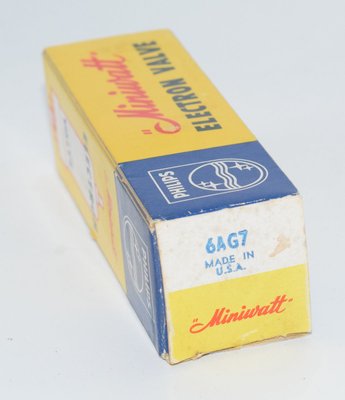
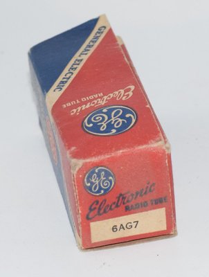
The 6AG7 was produced in very large quantities over many decades, and NOS (New Old Stock) examples remain readily available from tube dealers at moderate prices. GE, RCA, Sylvania, Raytheon, and Philips Miniwatt all produced the 6AG7, and military-spec VT-247 examples are also commonly found. The metal envelope construction means these tubes are physically robust and tend to survive storage well. GE NOS metal-envelope examples and Philips Miniwatt USA NOS metal-envelope examples are among the variants available to collectors and audio experimenters.
Practical Considerations for Audio Use
When using the 6AG7 in audio circuits, builders should be aware of several practical considerations:
- Heater supply: DC heater supply is recommended for audio use to minimize hum, as the 0.65A heater current is substantial and the high transconductance makes the tube sensitive to heater-induced noise.
- Socket quality: A high-quality octal socket is recommended, as the high transconductance means that any contact resistance variations can affect performance.
- Screen supply regulation: The datasheet recommends that when bias is obtained by the automatic background-control method, the screen voltage should be obtained from a source of good regulation. This advice applies equally to audio circuits.
- Mounting: Vertical mounting is preferred. If horizontal mounting is necessary, pins #2 and #7 (heater pins) should be in a vertical plane.
- Grid circuit resistance: The DC resistance in the grid circuit should not exceed 0.25 megohm with fixed bias or 1.0 megohm with self (cathode) bias.
- Output transformer: For SE audio output use, an output transformer with a primary impedance of approximately 5,000–10,000 ohms is typical, depending on the desired operating point and load matching requirements.