Introduction and History
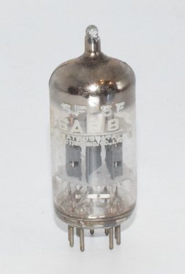
The 6AQ8, known in Europe under its Mullard-Philips designation ECC85, is a miniature dual triode vacuum tube designed primarily for VHF (very high frequency) applications. Developed in the mid-1950s, this tube was engineered to serve as a combined VHF amplifier and oscillator/mixer in FM radio and television front-end circuits. The tube was manufactured by numerous companies across Europe and Asia, including Philips (Miniwatt), Tesla Rožnov (Czechoslovakia), Matsushita (Japan), Valvo, Siemens, and others.
The ECC designation follows the Mullard-Philips naming convention: E = 6.3V heater, CC = double triode, and 85 = the specific type number in the series. The American RETMA designation 6AQ8 was assigned for the same tube type. The Tesla Rožnov datasheet, dated October 10, 1957, confirms that the Tesla ECC85 directly replaces the foreign type 6AQ8.
The 6AQ8/ECC85 was a workhorse of European FM receiver design throughout the late 1950s and 1960s. Its high transconductance, relatively low interelectrode capacitances, and separate cathode construction made it ideally suited for high-frequency front-end stages where low noise and stable oscillation were paramount. While originally designed for RF applications, this tube has found a second life in the audio community, where its unique sonic characteristics are valued by enthusiasts and amplifier designers.
Technical Specifications and Design
General Description
The 6AQ8/ECC85 is a dual triode with two electrically identical systems sharing a common envelope. Both triode sections have separate cathodes, and all electrodes including the internal shield are brought out to the base pins. The tube uses an all-glass miniature (Noval) construction with an oxide-coated cathode, indirectly heated. The heater can be powered by AC.
Physical Characteristics
| Parameter | Value |
|---|---|
| Base Type | Noval (B9A), 9-pin miniature |
| Envelope | All-glass miniature (T-6½ equivalent) |
| Mounting | Any position |
| Socket | S 9/12 (ČSN 35 8904) |
| Weight | Approximately 15 g |
| Maximum Overall Length | 56.3 mm |
| Maximum Diameter | 22.2 mm |
| Seated Height | 49.7 mm |
Pin Configuration (Bottom View)
| Pin | Function |
|---|---|
| 1 | Anode I (aI) |
| 2 | Grid I (gI) |
| 3 | Cathode I (kI) |
| 4 | Heater (f) |
| 5 | Heater (f) |
| 6 | Anode II (aII) |
| 7 | Grid II (gII) |
| 8 | Cathode II (kII) |
| 9 | Internal Shield (s) |
Heater Data
| Parameter | Symbol | Value | Unit |
|---|---|---|---|
| Heater Voltage | Uf | 6.3 | V |
| Heater Current | If | 0.435 | A |
The heater is indirectly heated with an oxide cathode, and parallel connection is used for AC supply operation.
Interelectrode Capacitances (per section, measured without external shield)
| Parameter | Symbol | Value | Unit |
|---|---|---|---|
| Grid to Anode (input to output) | Cga | 1.85 | pF |
| Grid to Cathode + Heater | Cg/k+f | 3.3 | pF |
| Anode to Cathode | Ca/k | 0.23 | pF |
| Anode to Cathode + Heater + Shield | Ca/k+f+s | 1.6 | pF |
| Anode I to Anode II | CaI/aII | 0.04 | pF |
| Anode I to Cathode II | CaI/kII | < 0.003 | pF |
| Grid I to Grid II | CgI/gII | 0.003 | pF |
| Anode I to Grid II | CaI/gII | < 0.008 | pF |
| Anode II to Grid I | CaII/gI | < 0.008 | pF |
| Anode II to Cathode I | CaII/kI | < 0.003 | pF |
| Grid I to Cathode II | CgI/kII | < 0.003 | pF |
| Grid II to Cathode I | CgII/kI | < 0.003 | pF |
Note: The verified reference data lists Cgk = 3.0 pF, Cak = 0.18 pF, and Cga = 1.5 pF. The Tesla datasheet specifies Cg/k+f = 3.3 pF (grid to cathode including heater), Ca/k = 0.23 pF (anode to cathode alone), and Ca/g = 1.85 pF (anode to grid). Minor differences reflect measurement conditions (with or without heater/shield connections). The extremely low cross-section capacitances between the two triode systems (all below 0.008 pF) demonstrate the excellent internal shielding between sections.
Characteristic Values (Ua = 250 V, per section)
| Parameter | Symbol | Value | Unit |
|---|---|---|---|
| Anode Voltage | Ua | 250 | V |
| Grid Bias Voltage | Ug1 | −2.3 | V |
| Cathode Resistor | Rk | 230 | Ω |
| Anode Current | Ia | 10 | mA |
| Transconductance (Mutual Conductance) | S (gm) | 5.9 | mA/V |
| Amplification Factor | μ | 57 | — |
| Plate Resistance (Internal Resistance) | Ri (rp) | 9.7 | kΩ |
| Drift (D) | D | 1.75 | % |
| Anode Current at Cutoff (Ug1 = −7 V) | Ia z | < 1 | mA |
Maximum Ratings (per section unless noted)
| Parameter | Symbol | Value | Unit |
|---|---|---|---|
| Anode Voltage (cold, no signal) | Uao | 550 | V max |
| Anode Voltage (operating) | Ua | 300 | V max |
| Anode Dissipation (per section) | Wa | 2.5 | W max |
| Combined Anode Dissipation (both sections) | WaI+WaII | 4.5 | W max |
| Cathode Current | Ik | 15 | mA max |
| Negative Grid Voltage | −Ug1 | 100 | V max |
| Grid Leak Resistance | Rg1 | 1 | MΩ max |
| Cathode-to-Heater Voltage (DC or peak AC) | Ek/f | 90 | V max |
| External Cathode-to-Heater Resistance | Rk/f | 20 | kΩ max |
| Grid Voltage for Grid Current Onset (Ig1 = +0.3 μA) | Ug1i | −1.3 | V max |
VHF Amplifier Operating Conditions
| Parameter | Symbol | Value | Unit |
|---|---|---|---|
| Supply Voltage | Ub | 250 | V |
| Anode Load Resistor | Ra | 1.8 | kΩ |
| Anode Voltage | Ua | 230 | V |
| Grid Bias | Ug1 | −2 | V |
| Anode Current | Ia | 10 | mA |
| Transconductance | S | 6 | mA/V |
| Internal Resistance | Ri | 9.7 | kΩ |
| Cathode Resistor | Rk | 200 | Ω |
| Input Impedance (f = 100 Mc/s) | Xg1 | 6 | kΩ |
| Equivalent Noise Resistance | Rekv | ~500 | Ω |
Note: The anode load resistor Ra must be bypassed with a 1 kpF capacitor for high-frequency operation.
Self-Oscillating Mixer Operating Conditions
| Parameter | Symbol | Value | Unit |
|---|---|---|---|
| Supply Voltage | Ub | 250 | V |
| Anode Load Resistor | Ra | 12 | kΩ |
| Anode Voltage | Ua | 187 | V |
| Grid Leak Resistance | Rg1 | 1 | MΩ |
| Anode Current | Ia | 5.2 | mA |
| Internal Resistance | Ri | 22 | kΩ |
| Oscillation Voltage | Eosc | 3 | Vef |
| Conversion Transconductance | Sc | 2.3 | mA/V |
| MF Transconductance (0.1 Vef on g1) | Smf | 2.8 | mA/V |
| Input Impedance (f = 100 Mc/s) | Xg1 | ~15 | kΩ |
To prevent microphonics in the oscillator circuit, no connection should be made between the heater filament and the cathode at audio frequencies.
Applications and Usage
The 6AQ8/ECC85 was designed for and widely used in the following applications:
- VHF/FM Radio Front-Ends: The primary application. One triode section serves as a grounded-grid VHF amplifier (System I), while the second section operates as a self-oscillating mixer (System II). This was the standard front-end configuration in European FM receivers of the late 1950s and 1960s. The Tesla datasheet shows a complete application circuit for FM reception at 10.7 Mc/s IF.
- Television Tuners: Used in TV front-end circuits for FM and television signal reception, where its low noise figure and high transconductance at VHF frequencies were advantageous.
- VHF Amplifiers: The high transconductance of 6 mA/V in the amplifier configuration, combined with the relatively low equivalent noise resistance of approximately 500 Ω, made it suitable for sensitive VHF preamplifier stages.
- Frequency Converters and Mixers: The conversion transconductance of 2.3 mA/V and the ability to self-oscillate made it an effective mixer/oscillator combination.
- Audio Preamplifiers and Line Stages: While not originally designed for audio, the tube's high μ of 57, moderate plate resistance of 9.7 kΩ, and good transconductance have made it attractive for audio applications, particularly in line-level amplification stages.
Sound Characteristics
The 6AQ8/ECC85, while originally an RF tube, has developed a following among audiophiles who appreciate its distinctive sonic signature. Its sound character differs notably from the more commonly used audio dual triodes like the ECC83/12AX7 or ECC82/12AU7, owing to its different electrical parameters — particularly the combination of a moderately high amplification factor (μ = 57) with a relatively low plate resistance (9.7 kΩ) and high transconductance (5.9 mA/V).
Audiophiles and engineers who have used the 6AQ8/ECC85 in audio circuits generally describe its sound as follows:
- Open and Airy Treble: The tube's VHF heritage translates into an extended, detailed high-frequency response. The treble is often described as having excellent air and sparkle without becoming harsh or fatiguing. This is partly attributable to the low interelectrode capacitances (Cga = 1.85 pF, Ca/k = 0.23 pF), which minimize high-frequency rolloff in audio circuits.
- Fast and Dynamic: The high transconductance of 5.9 mA/V gives the tube excellent transient response. Listeners note a sense of speed and immediacy, with sharp attack on percussive instruments and a lively, engaging presentation.
- Detailed Midrange: The midrange is typically described as clear, articulate, and slightly forward compared to warmer-sounding types like the ECC83. Vocal reproduction is noted for its clarity and presence.
- Lean but Controlled Bass: The relatively low plate resistance allows good current delivery, resulting in controlled bass response. However, compared to lower-μ types like the ECC82, the bass may be perceived as slightly leaner or tighter rather than full and warm.
- Lower Noise Floor: With an equivalent noise resistance of approximately 500 Ω, the 6AQ8 can offer a quiet background, though this is highly dependent on the specific specimen and manufacturer. NOS examples from Philips Miniwatt (Holland) are particularly prized for their low noise characteristics.
- Manufacturer Variations: As with most vacuum tubes, sonic character varies between manufacturers. Philips Miniwatt Holland examples are considered among the finest, offering a refined, balanced sound. Tesla Rožnov tubes tend to be robust and reliable with a slightly more forward presentation. Matsushita (Japan) examples offer good value with clean, neutral characteristics.
Overall, the 6AQ8/ECC85 occupies a sonic middle ground — it is more detailed and dynamic than the ECC82/12AU7, while being less gainy and potentially less microphonic than the ECC83/12AX7. Its character suits listeners who prefer clarity and detail over warmth and euphonic coloration.
Equivalent and Substitute Types
The following types are related to the 6AQ8/ECC85, but care must be taken when substituting:
Direct Equivalents
| Type | Notes |
|---|---|
| ECC85 | European (Mullard-Philips) designation — identical tube. This is the primary designation used by European manufacturers including Philips, Mullard, Valvo, Siemens, Tesla, and others. |
| 6AQ8 | American RETMA designation — identical tube. |
Different Rating Substitutes (NOT Drop-In Replacements)
The following types are related but have different ratings, pinouts, or operating parameters. They should not be considered direct drop-in replacements without circuit modification:
| Type | Notes |
|---|---|
| 6CC43 | Different rating substitute — verify specifications before use. |
| 6L12 | Different rating substitute — verify specifications before use. |
| B719 | Different rating substitute — verify specifications before use. |
Important: The 6AQ8/ECC85 should not be confused with the ECC88/6DJ8 or ECC81/12AT7, which are sometimes suggested as alternatives. While all are dual triodes on Noval bases, they have significantly different operating parameters, pinouts (in the case of 12-volt heater types), and bias requirements. Always verify the specific circuit requirements before substituting any tube type.
Notable Characteristics
- Separate Cathodes: Unlike some dual triodes where cathodes are internally connected, the 6AQ8/ECC85 has completely separate cathode connections for each triode section. This provides maximum flexibility in circuit design, allowing each section to operate at different bias points or in entirely different circuit configurations.
- Internal Shield: The tube features an internal electrostatic shield between the two triode sections, brought out to pin 9. This shield provides excellent isolation between sections, with cross-capacitances below 0.008 pF. This is critical for its intended use as a combined VHF amplifier and oscillator, where coupling between sections must be minimized.
- High Cold Anode Voltage Rating: The maximum anode voltage with no signal (cold) is an impressive 550 V, while the operating maximum is 300 V. This provides a generous safety margin in most applications.
- Combined Dissipation Limit: While each section can dissipate up to 2.5 W, the combined dissipation of both sections must not exceed 4.5 W. This means that if one section is operated at full dissipation, the other must be limited to 2.0 W.
- High Amplification Factor: With μ = 57, the 6AQ8 sits between the ECC82 (μ ≈ 17) and the ECC83 (μ ≈ 100) in terms of voltage gain capability, making it versatile for various gain stage requirements.
- Favorable Transconductance-to-Plate-Resistance Ratio: The combination of S = 5.9 mA/V and Ri = 9.7 kΩ gives the tube good driving capability. The relatively low plate resistance means it can drive subsequent stages or moderate capacitive loads more effectively than higher-impedance types.
- Low Interelectrode Capacitances: Designed for VHF operation, the tube's capacitances are notably low — particularly the anode-to-cathode capacitance of just 0.23 pF and the grid-to-anode capacitance of 1.85 pF. In audio applications, this translates to excellent high-frequency bandwidth.
- Microphony Considerations: The Tesla datasheet specifically warns against connecting the heater to the cathode at audio frequencies in oscillator circuits to prevent microphonics. In audio applications, careful attention to mounting and vibration isolation is recommended, as with most miniature triodes designed for RF service.
Usage in the Audio Community
The 6AQ8/ECC85 has carved out a niche in the audio community, though it remains less well-known than mainstream audio dual triodes. Its adoption has been driven by several factors:
Line Stage Preamplifiers
The 6AQ8's μ of 57 makes it well-suited for line-stage preamplifier designs where moderate gain is needed. It provides more gain than an ECC82/12AU7 (μ ≈ 17) while being more manageable than an ECC83/12AX7 (μ ≈ 100). Several boutique amplifier manufacturers have designed line stages around this tube, taking advantage of its combination of gain, low plate resistance, and excellent bandwidth.
Phono Stages
Some designers have employed the 6AQ8 in phono preamplifier circuits, where its high transconductance contributes to a favorable signal-to-noise ratio. The separate cathodes allow each section to be optimized independently — for example, one section for RIAA equalization gain and the other for output buffering.
Headphone Amplifiers
The relatively low plate resistance of 9.7 kΩ makes the 6AQ8 a reasonable candidate for headphone amplifier output stages, particularly when driving higher-impedance headphones (300Ω and above). The tube can deliver adequate current swing for comfortable listening levels.
DAC Output Stages
In hybrid digital-to-analog converter designs, the 6AQ8 has been used as a tube output buffer stage. Its wide bandwidth (a consequence of its VHF design heritage) ensures that it does not limit the high-frequency performance of modern DAC chips, while adding the desired tube character to the signal path.
Guitar Amplifiers
While not a standard guitar amplifier tube, some boutique and custom guitar amp builders have experimented with the 6AQ8 as a preamp tube. Its gain characteristics and tonal profile offer a different voicing compared to the ubiquitous 12AX7, and adventurous players seeking unique tones have explored this option. Note that the 6AQ8 has a 6.3V heater (not 12.6V like the 12AX7) and different pinout, so it cannot be directly substituted without circuit modifications.
Collectibility and Market
NOS (New Old Stock) examples of the 6AQ8/ECC85 are available on the vintage tube market, often at more reasonable prices than premium audio types like the ECC83 or ECC88. Philips Miniwatt Holland production from the early 1960s is particularly sought after, with collectors noting strong test results and excellent build quality. Matsushita (Japan) production offers a more affordable alternative. Tesla Rožnov examples are valued for their robust construction and consistent performance.
The relative obscurity of the 6AQ8 in audio circles means that high-quality NOS specimens can sometimes be found at bargain prices compared to more fashionable tube types — making it an attractive option for the knowledgeable tube audio enthusiast willing to design or modify circuits to accommodate its specific requirements.
Design Considerations for Audio Use
When designing audio circuits around the 6AQ8/ECC85, engineers should note:
- The typical operating point for audio use would be Ua = 250 V, Ia = 10 mA, Ug1 = −2.3 V with a 230 Ω cathode resistor — as specified in the characteristic values.
- The maximum grid leak resistance is 1 MΩ, which is adequate for most audio coupling arrangements.
- The grid current onset voltage of −1.3 V means that signal swings must be kept well below this threshold to avoid grid current distortion in Class A operation.
- The combined anode dissipation limit of 4.5 W for both sections must be respected when both triodes are used simultaneously in a stereo or cascaded configuration.
- The internal shield (pin 9) should be connected to ground or a suitable reference point to maintain low crosstalk between sections — particularly important in stereo applications where each section handles a different channel.