1. Introduction and History
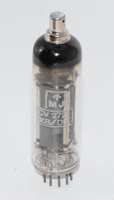
The 6CJ6 is a line time base and sound output pentode developed in the early 1950s, with the Philips datasheet dated August 8, 1951 (from RTMA release #1029, October 16, 1951). Manufactured by N.V. Philips' Gloeilampenfabrieken in Eindhoven, Holland, the 6CJ6 was designed primarily for two demanding applications in television receivers: horizontal (line) deflection output stages and audio output stages. Its European designation is the EL81, and it carries the military/CV designation CV2721 (also referenced as CV10326).
The 6CJ6 belongs to a family of robust output pentodes that emerged during the rapid expansion of television broadcasting in the late 1940s and early 1950s. Television sets of this era required tubes capable of handling high peak voltages and currents in the line output stage while also being suitable for the audio section — a dual-purpose design philosophy that reduced manufacturing costs and simplified spare parts inventories. The tube's ability to withstand peak surge plate voltages of 7,000 volts made it particularly well-suited for the demanding environment of horizontal deflection circuits, where flyback pulses generate extremely high voltage transients.
Philips and its associated brands (Mullard in the UK, Amperex in the US, and Valvo in Germany) were the primary manufacturers, though other companies produced equivalent types under license. The tube saw widespread use throughout Europe, Australia, and New Zealand in television receivers from the early 1950s through the mid-1960s, when solid-state replacements began to take over.
2. Technical Specifications and Design
Physical Specifications
| Parameter | Value |
|---|---|
| Cathode | Coated unipotential |
| Base | Small button noval 9-pin (B9A / Noval) — JETEC basing designation 9AS |
| Bulb | T6½ |
| Maximum overall length | 3 3/16" |
| Maximum seated height | 2 15/16" |
| Bulb length excluding top cap | 2 7/16" ± 3/32" |
| Maximum diameter | 7/8" |
| Mounting position | Any |
Pin Configuration (Bottom View of Base)
| Pin | Connection |
|---|---|
| Pin 1 | Internally connected (no external connection) |
| Pin 2 | Grid No. 1 (Control Grid) |
| Pin 3 | Cathode |
| Pin 4 | Heater |
| Pin 5 | Heater |
| Pin 6 | Internally connected (no external connection) |
| Pin 7 | Internally connected (no external connection) |
| Pin 8 | Grid No. 2 (Screen Grid) |
| Pin 9 | Grid No. 3 (Suppressor Grid) |
| Top Cap | Plate (Anode) |
Important note: Pins 1, 6, and 7 are internal connections and must not be used for external wiring. The plate connection is brought out to a top cap, which is a skirted miniature type rated at 250°±005". This top-cap arrangement was essential for the high-voltage line output application, providing adequate insulation between the plate terminal and the lower-voltage base pins.
Heater Data
| Parameter | Value |
|---|---|
| Heater voltage | 6.3 volts |
| Heater current | 1.05 amps |
Direct Interelectrode Capacitances
| Parameter | Value |
|---|---|
| Grid No. 1 to all other electrodes | 14.7 pF |
| Plate to all other electrodes | 6.0 pF |
| Plate to Grid No. 1 | max. 0.8 pF |
| Plate to cathode | max. 0.1 pF |
| Grid No. 1 to heater | max. 0.2 pF |
Maximum Ratings (Design Center Values)
| Parameter | Value |
|---|---|
| Plate voltage (without current) | max. 550 volts |
| Peak positive surge plate voltage | max. 7,000 volts * |
| Peak negative surge plate voltage | max. 7,000 volts * |
| Average plate voltage | max. 300 volts |
| Plate dissipation | max. 8.0 watts |
| Grid No. 2 dissipation | max. 4.5 watts |
| Plate dissipation + Grid No. 2 dissipation | max. 10 watts |
| Grid No. 2 voltage (without current) | max. 550 volts |
| Grid No. 2 voltage | max. 300 volts |
| Cathode current | max. 180 mA |
| Grid No. 1 voltage at Grid No. 1 current = +0.3 µA (current starting point) | max. −1.3 volts |
| Grid No. 1 circuit resistance | max. 0.5 megohm |
| External resistance between heater and cathode | max. 20,000 ohms |
| Voltage between heater and cathode | max. 100 volts |
* Maximum permissible pulse duration 18% of one cycle, with a maximum of 18 µsec.
Typical Characteristics (at stated operating point)
| Parameter | Value |
|---|---|
| Plate voltage | 250 volts |
| Grid No. 3 voltage | 0 volt |
| Grid No. 2 voltage | 250 volts |
| Grid No. 1 voltage | −38.5 volts |
| Plate current | 32 mA |
| Grid No. 2 current | 2.4 mA |
| Transconductance (gm) | 4,600 µmhos (4.6 mA/V) |
| Plate resistance (rp) | 15,000 ohms |
| Amplification factor of Grid No. 2 with respect to Grid No. 1 | 5.1 |
From the typical characteristics, we can derive the amplification factor (µ) as the product of transconductance and plate resistance: µ = gm × rp = 4.6 mA/V × 15,000 Ω = 69 (approximately). Note that this is the µ with respect to the control grid and plate; the amplification factor of Grid No. 2 with respect to Grid No. 1 is 5.1 as stated in the datasheet.
Single-Ended Audio Operating Point
At the typical operating point (Va = 250V, Vg2 = 250V, Vg1 = −38.5V), the 6CJ6 delivers approximately 3.3 watts of output power in single-ended Class A operation with a plate load impedance of approximately 7,800 ohms and total harmonic distortion of around 10%.
3. Applications and Usage
Line Time Base (Horizontal Deflection) Output
The primary application for the 6CJ6 was as a line (horizontal) output valve in television receivers. In this role, the tube drives the horizontal deflection yoke and the EHT (Extra High Tension) transformer to generate the high voltage needed for the CRT anode. The tube's ability to withstand peak surge voltages of 7,000 volts (both positive and negative) during the flyback period made it ideal for this demanding service.
The Philips datasheet provides specific guidance for line time base output stages: to allow for tube spread and deterioration during life, the circuit should be designed around a peak anode current not exceeding:
- 250 mA at a plate voltage of 70V and Grid No. 2 voltage of 170V, or
- 310 mA at a plate voltage of 70V and Grid No. 2 voltage of 200V
The peak anode current of an average new tube at a plate voltage of 70V and a Grid No. 1 voltage of −1V is:
- 380 mA at a Grid No. 2 voltage of 170V
- 470 mA at a Grid No. 2 voltage of 200V
Sound (Audio) Output
The 6CJ6 was also widely used as the audio output valve in television receivers, often in single-ended Class A configuration driving a small loudspeaker through an output transformer. In this application, the tube typically operated at 250V on both plate and screen with a bias of −38.5V, delivering modest but adequate power for television sound reproduction.
Push-Pull Class B Audio Amplifier
The Philips datasheet provides detailed operating characteristics for two 6CJ6 tubes in push-pull Class B configuration:
Configuration 1: 170V Supply
| Parameter | Value |
|---|---|
| Plate voltage | 170 volts |
| Grid No. 3 voltage | 0 volt |
| Grid No. 2 voltage | 170 volts |
| Common Grid No. 2 resistor | 1,000 ohms |
| Grid No. 1 voltage | −27 volts |
| Load resistance (plate to plate) | 2,500 ohms |
| Output power | 13.5 watts |
| Total distortion | 5.5% |
| Plate current (quiescent / max signal) | 2×20 / 2×73 mA |
| Grid No. 2 current (quiescent / max signal) | 2×1.5 / 2×10 mA |
| Input AC voltage (RMS) | 19 volts |
Configuration 2: 200V Supply
| Parameter | Value |
|---|---|
| Plate voltage | 200 volts |
| Grid No. 3 voltage | 0 volt |
| Grid No. 2 voltage | 200 volts |
| Common Grid No. 2 resistor | 1,000 ohms |
| Grid No. 1 voltage | −31.5 volts |
| Load resistance (plate to plate) | 2,500 ohms |
| Output power | 20 watts |
| Total distortion | 5.5% |
| Plate current (quiescent / max signal) | 2×25 / 2×87 mA |
| Grid No. 2 current (quiescent / max signal) | 2×2.0 / 2×12.5 mA |
| Input AC voltage (RMS) | 22.5 volts |
The push-pull Class B configuration at 200V is particularly noteworthy, delivering a substantial 20 watts of output power at 5.5% THD — impressive performance for a pair of relatively compact noval-based pentodes.
4. Sound Characteristics
The 6CJ6 / EL81 occupies an interesting sonic niche among output pentodes. While it was designed primarily as a television tube rather than a dedicated audio valve, its electrical characteristics lend it a distinctive voice that has attracted attention from adventurous audio enthusiasts.
Tonal Character
In single-ended Class A operation, the 6CJ6 produces a sound that is characteristically warm and slightly forward in the midrange. The relatively high transconductance of 4,600 µmhos combined with a moderate plate resistance of 15,000 ohms gives the tube good control over the output transformer, resulting in a presentation that is more articulate than some lower-gm pentodes. The midrange has a pleasant density and body that works particularly well with vocal material and acoustic instruments.
The bass response tends to be firm rather than lush — the tube doesn't produce the deep, pillowy low end of larger beam tetrodes like the 6L6 or KT66, but it offers respectable weight and definition for its power class. The treble is smooth and slightly rolled off at the extremes, which can be forgiving with brighter source material or harder-edged digital recordings.
Dynamic Behavior
The 6CJ6's heritage as a line output tube means it was designed to handle rapid signal transitions and high peak currents. This translates into good transient response and dynamic punch in audio applications — the tube can snap to attention quickly and handle percussive material with authority that belies its modest 3.3-watt single-ended output rating. The tube's ability to handle peak currents well above its quiescent operating point gives it a sense of headroom and ease that is appreciated in dynamic passages.
Distortion Character
Like most pentodes, the 6CJ6 produces a mix of even and odd harmonics when driven into distortion. In single-ended operation, the even-order harmonics predominate at lower signal levels, contributing to the warm, musical quality. As the tube is driven harder, odd-order harmonics become more prominent. The 10% THD figure at rated output in single-ended mode is typical for a pentode of this class, and many builders find that operating the tube at reduced power levels (1–2 watts) yields a much more refined harmonic signature.
In push-pull Class B configuration, the cancellation of even-order harmonics results in a cleaner, more neutral presentation, though some listeners find this less characterful than the single-ended sound. The 5.5% THD at full output in push-pull is quite respectable and drops significantly at lower power levels.
Comparison to Other Pentodes
Sonically, the 6CJ6 sits somewhere between the EL84/6BQ5 and the EL34 in character — it has more authority and weight than the EL84 but lacks the sheer power and bass extension of the EL34. Its midrange presentation has been described as having a slightly "British" character, which is perhaps unsurprising given its Philips/Mullard heritage. The top-cap plate connection, while mechanically inconvenient, does provide excellent isolation between the plate circuit and the input, which can contribute to a lower noise floor and cleaner high-frequency performance.
5. Equivalent and Substitute Types
| Type Designation | Manufacturer / Origin | Notes |
|---|---|---|
| EL81 | Philips / Mullard / European | Direct equivalent — the European Pro-Electron designation for the same tube. Identical pinout, ratings, and characteristics. The "E" prefix denotes 6.3V heater, "L" denotes output pentode. |
| CV2721 | UK Military (CV Register) | Direct equivalent — the British military Common Valve designation for the EL81/6CJ6. Selected and tested to military standards but electrically identical. |
| CV10326 | UK Military (CV Register) | Another CV designation associated with this tube type. |
Important notes on substitution: The 6CJ6 / EL81 has a top-cap plate connection, which limits direct physical substitution with other output pentodes that use all-pin base connections (such as the EL84). Any amplifier designed for the 6CJ6 must accommodate the top-cap anode lead. The noval (B9A) base and top-cap arrangement is specific to this tube family, and there are no widely available pin-compatible substitutes outside the EL81/CV2721 family.
The 6CJ6 should not be confused with the 6CL6, 6CM6, or other similarly numbered tubes — these have different characteristics, pinouts, and ratings. Always verify the exact type designation before substitution.
6. Notable Characteristics
Top-Cap Plate Connection
One of the most distinctive physical features of the 6CJ6 is its top-cap plate connection. While this adds mechanical complexity to amplifier construction, it was an essential design choice for the line output application where the plate sees peak voltages of up to 7,000 volts. The physical separation between the high-voltage plate terminal and the low-voltage base pins provides critical insulation and reduces the risk of internal arcing. For audio applications, this arrangement also provides excellent isolation between the output and input circuits, potentially reducing feedback and improving stability.
Exceptional Voltage Handling
The 7,000-volt peak surge rating (both positive and negative) is remarkable for a tube of this physical size. This rating, while primarily relevant to line output service, speaks to the robust internal construction of the tube — heavy-duty plate and grid structures, generous spacing between elements, and high-quality insulation. This ruggedness translates into long life and reliable operation in audio applications where the tube operates well within its design limits.
Combined Dissipation Limit
The datasheet specifies a combined plate + screen dissipation limit of 10 watts, with individual limits of 8 watts for the plate and 4.5 watts for the screen. This combined limit is important for circuit designers to observe — it means that if the plate is dissipating its full 8 watts, the screen dissipation must be kept below 2 watts, and vice versa.
Internal Connections
Pins 1, 6, and 7 are internally connected within the tube. Circuit designers must be aware of these internal connections and ensure that no external wiring is connected to these pins, as doing so could create short circuits or other problems. These internal connections are typically used for internal shielding or structural support within the tube.
Low Screen Current
The 6CJ6 exhibits a notably low screen-to-plate current ratio. At the typical operating point, the screen current is only 2.4 mA compared to 32 mA of plate current — a ratio of approximately 1:13. This efficient electron beam focusing means less wasted power in the screen circuit and contributes to the tube's relatively high efficiency for a pentode of its class.
Grid No. 1 Current Starting Point
The datasheet specifies that the Grid No. 1 voltage at which grid current reaches +0.3 µA is a maximum of −1.3 volts. This is an important parameter for amplifier designers, as it defines the boundary beyond which the control grid begins to draw current. Operating the tube with grid voltage more positive than this point will load the driver stage and introduce additional distortion. The maximum grid circuit resistance of 0.5 megohm must also be observed to prevent grid current from causing bias shift.
7. Usage in the Audio Community
Historical Context
The 6CJ6 / EL81 was never a mainstream audio tube in the way that the EL34, EL84, or 6L6 were. Its primary market was always television, and most of the millions of units produced went into TV sets rather than audio amplifiers. However, this television heritage has become something of an advantage in the modern era — large quantities of NOS (New Old Stock) 6CJ6 and EL81 tubes remain available at prices significantly below those commanded by more popular audio tubes, making them attractive to budget-conscious builders and experimenters.
DIY and Custom Amplifier Projects
The 6CJ6 has found a following among DIY amplifier builders who appreciate its combination of respectable performance, low cost, and interesting sonic character. The tube is particularly well-suited to:
- Low-power single-ended amplifiers: At approximately 3.3 watts in Class A single-ended operation, the 6CJ6 is well-matched to high-efficiency speakers (95 dB/W/m and above). These amplifiers offer the classic single-ended pentode sound with good dynamics and a warm, engaging midrange.
- Push-pull amplifiers: A pair of 6CJ6 tubes in push-pull Class B can deliver up to 20 watts at 200V supply — enough power to drive most bookshelf and many floor-standing speakers. The 13.5-watt configuration at 170V is also popular, as it operates the tubes more conservatively and may offer improved longevity.
- Experimental and educational projects: The tube's comprehensive datasheet with multiple characteristic curves makes it an excellent choice for students and experimenters learning about pentode operation and amplifier design.
Guitar Amplifier Applications
Some guitar amplifier builders have experimented with the 6CJ6 as an output tube, particularly in smaller practice amplifiers. The tube's dynamic response and harmonic character when driven into distortion can produce interesting overdrive tones. The 3.3-watt single-ended output is ideal for bedroom and studio practice amplifiers where full power tube saturation at manageable volume levels is desired. The top-cap connection adds a vintage aesthetic that appeals to some builders.
Mullard-Branded NOS Tubes
Among collectors and audiophiles, Mullard-manufactured EL81 / CV2721 / 6CJ6 tubes are the most sought-after variants. Mullard's reputation for consistent quality and musical sound extends to this tube type, and NOS Mullard EL81s command a premium over generic or unbranded examples. These tubes are identifiable by Mullard's characteristic factory codes and construction details.
Practical Considerations for Audio Use
Builders considering the 6CJ6 for audio projects should be aware of several practical considerations:
- Top-cap connection: The plate connection via top cap requires appropriate clip leads and chassis layout considerations. High-quality top-cap connectors should be used, and adequate clearance must be maintained between the top-cap lead and other components.
- Output transformer selection: For single-ended operation, an output transformer with a primary impedance of approximately 7,800 ohms is optimal. For push-pull Class B, a center-tapped primary with 2,500 ohms plate-to-plate is specified.
- Bias requirements: The −38.5V control grid bias at the typical operating point requires a reasonably substantial bias supply. Cathode bias with a resistor of approximately 1,200 ohms (for the single-ended operating point) is a common approach, though fixed bias offers more precise control.
- Heater current: At 1.05 amps, the 6CJ6 draws more heater current than an EL84 (0.76A) but less than an EL34 (1.5A). Power transformer heater windings must be rated accordingly.
- Driver requirements: With a bias of −38.5V and requiring approximately 19–22.5V RMS of drive signal for full push-pull output, the 6CJ6 needs a reasonably capable driver stage. A medium-mu triode such as a 12AU7 or 12AT7, or a pentode voltage amplifier, is typically adequate.
Availability and Market
As of recent years, NOS 6CJ6 / EL81 tubes remain available from specialty tube dealers, often at moderate prices compared to more popular audio output tubes. The tube was produced in large quantities for the television market, and significant stocks remain. Brands to look for include Philips, Mullard, Amperex, Valvo, Siemens, and various Eastern European manufacturers. Testing before use is always recommended with NOS tubes, particularly checking for adequate emission, low gas content, and absence of grid current at the specified bias point.
The 6CJ6 represents an excellent value proposition for the audio experimenter: a well-documented, robustly constructed output pentode with genuine sonic merit, available at a fraction of the cost of more fashionable audio tubes. Its television heritage, far from being a limitation, has ensured both plentiful supply and a level of ruggedness that serves audio applications well.