Introduction and History
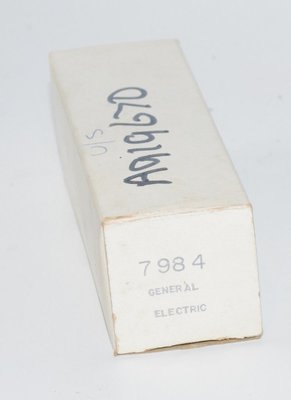
The 7984 is a Compactron beam pentode designed by General Electric for use as a radio-frequency power amplifier in mobile communications equipment. Introduced in the early 1960s (the GE datasheet is dated September 1964, with characteristic curves dated August 14, 1962), the 7984 was part of GE's innovative Compactron tube family — a line of multi-pin, large-envelope tubes that represented one of the last major advances in vacuum tube technology before the widespread adoption of solid-state devices.
The Compactron format, with its 12-pin base, allowed GE engineers to incorporate features that were difficult to achieve in smaller envelopes: single-ended construction, low seated height, short internal leads, multiple cathode and screen connections, and low driving-power requirements. The 7984 was specifically optimized for Class C RF power amplifier and oscillator service at frequencies up to 175 megacycles, where it could deliver a remarkable power output of up to 46 watts under Intermittent Mobile Service (IMS) conditions.
Manufactured by General Electric at their Tube Department in Owensboro, Kentucky, and also produced by Sylvania, the 7984 served primarily in commercial and amateur radio transmitter applications during the 1960s. Its combination of high power output, compact size, and relatively low drive requirements made it an attractive choice for mobile and portable RF equipment of the era.
Technical Specifications and Design
Heater Characteristics
| Parameter | Value |
|---|---|
| Heater Voltage (AC or DC) | 13.5 ±1.5 Volts |
| Heater Current (at Ef = 13.5V) | 0.58 Amperes |
| Cathode Type | Coated Unipotential |
Direct Interelectrode Capacitances (without external shield)
| Parameter | Value |
|---|---|
| Grid-Number 1 to Plate (g1 to p) | 0.16 pF |
| Input: g1 to (h + k + g2 + b.p.) | 16 pF |
| Output: p to (h + k + g2 + b.p.) | 6.0 pF |
Average Characteristics
| Parameter | Value |
|---|---|
| Plate Voltage | 200 Volts |
| Screen Voltage | 125 Volts |
| Grid-Number 1 Voltage | −7.5 Volts |
| Plate Current | 125 Milliamperes |
| Screen Current | 4.5 Milliamperes |
| Transconductance (gm) | 13,500 Micromhos |
Note: The manufacturer datasheet does not explicitly list amplification factor (μ) or plate resistance (rp) as separate specifications. These values can be derived from the published plate characteristic curves. The transconductance of 13,500 µmhos is exceptionally high, indicating a tube with very high gain capability.
Absolute-Maximum Ratings — RF Power Amplifier and Oscillator (Class C Telegraphy / Class C FM Telephony)
| Parameter | CCS | ICAS | IMS | Units |
|---|---|---|---|---|
| DC Plate Voltage | 600 | 750 | 750 | Volts |
| DC Screen Voltage | 250 | 250 | 250 | Volts |
| DC Grid-Number 1 Voltage | −100 | −100 | −100 | Volts |
| DC Plate Current | 150 | 150 | 180 | Milliamperes |
| DC Grid-Number 1 Current | 6.0 | 6.0 | 6.0 | Milliamperes |
| Screen Input | 3.0 | 3.0 | 3.0 | Watts |
| Plate Dissipation | 20 | 25 | 35 | Watts |
| Peak Heater-Cathode Voltage (Positive) | 100 | 100 | 100 | Volts |
| Peak Heater-Cathode Voltage (Negative) | 100 | 100 | 100 | Volts |
| Bulb Temperature at Hottest Point | 220 | 220 | 220 | °C |
Service Rating Definitions:
- CCS (Continuous Commercial Service): Normal tube life and reliability under continuous operating conditions are the prime consideration.
- ICAS (Intermittent Commercial and Amateur Service): Applications where minimum size, light weight, and considerably increased power output are prioritized. Life expectancy may be one-half that obtained in CCS.
- IMS (Intermittent Mobile Service): Applications such as aircraft where exceedingly high power output for short intervals is the primary requirement. Maximum "on" periods of 15 seconds followed by "off" periods of at least 60 seconds.
Typical Operation as Class C Amplifier at 175 Megacycles
| Parameter | CCS | ICAS | IMS | Units |
|---|---|---|---|---|
| Frequency | 175 | 175 | 175 | Megacycles |
| DC Plate Voltage | 315 | 375 | 450 | Volts |
| DC Screen Voltage | 165 | 160 | 200 | Volts |
| DC Grid-Number 1 Voltage (approx.) | −74 | −80 | −60 | Volts |
| Grid-Number 1 Resistor | 20,000 | 20,000 | 15,000 | Ohms |
| DC Plate Current | 150 | 150 | 180 | Milliamperes |
| DC Screen Current | 8.5 | 8.5 | 12 | Milliamperes |
| DC Grid-Number 1 Current (approx.) | 3.7 | 4 | 4 | Milliamperes |
| Driving Power (approx.) | 2 | 2 | 2 | Watts |
| Power Output (approx.) | 26.5 | 32 | 46 | Watts |
Note: Power output figures represent the power output of the tube itself. Power measured at the load will be less because of tank-circuit losses.
Mechanical Specifications
| Parameter | Value |
|---|---|
| Operating Position | Any |
| Envelope | T-12, Glass |
| Base | E12-74, Button 12-Pin (Compactron) |
| Outline Drawing | EIA 12-56 |
| Maximum Diameter | 1.563 Inches |
| Maximum Over-all Length | 2.875 Inches |
| Maximum Seated Height | 2.500 Inches |
Pin Connections (EIA 12EU Basing)
| Pin | Connection |
|---|---|
| Pin 1 | Heater |
| Pin 2 | Cathode and Beam Plates |
| Pin 3 | Plate (connect pins 3, 4, 5 together) |
| Pin 4 | Plate (connect pins 3, 4, 5 together) |
| Pin 5 | Plate (connect pins 3, 4, 5 together) |
| Pin 6 | Cathode and Beam Plates |
| Pin 7 | Grid Number 2 (Screen) |
| Pin 8 | Cathode and Beam Plates |
| Pin 9 | Cathode and Beam Plates |
| Pin 10 | Grid Number 1 (Control Grid) |
| Pin 11 | Grid Number 2 (Screen) |
| Pin 12 | Heater |
Important: Socket contacts for pins 3, 4, and 5 (the three plate pins) should be connected together. Similarly, the multiple cathode/beam plate connections (pins 2, 6, 8, 9) and the dual screen connections (pins 7, 11) are designed to reduce internal lead inductance — a critical consideration at VHF frequencies up to 175 MHz.
Applications and Usage
Original Design Intent
The 7984 was specifically designed for radio-frequency power amplifier service in mobile communications equipment. Its primary application was as a Class C RF power amplifier and oscillator operating at frequencies up to 175 megacycles (MHz). This placed it squarely in the VHF band used by commercial mobile radio, public safety communications, and amateur radio operations.
Key Application Areas
- Mobile Radio Transmitters: The tube's primary market was in VHF mobile communications equipment for commercial, public safety, and military applications. The 13.5V heater voltage was specifically chosen for compatibility with 12V vehicle electrical systems (with appropriate regulation).
- Amateur Radio: Under ICAS ratings, the 7984 could deliver 32 watts of RF power output at 175 MHz, making it attractive for amateur VHF transmitter projects. The relatively low drive requirement of approximately 2 watts made it easy to excite with modest driver stages.
- Aircraft Communications: Under IMS ratings, the tube could produce 46 watts for short transmission periods, ideal for aircraft push-to-talk communications where transmissions are brief and duty cycles are low.
- VHF Oscillators: The tube's characteristics also suited it for use as a power oscillator in VHF equipment.
Design Advantages
Several features made the 7984 particularly well-suited to its intended applications:
- Low Driving Power: Only approximately 2 watts of drive power was needed across all service ratings, simplifying transmitter design.
- Short Internal Leads: The multiple pin connections for plate, cathode, and screen grid were specifically designed to minimize internal lead inductance, which is critical for stable VHF operation.
- Single-Ended Construction: All connections are made through the base, simplifying socket and chassis design.
- Low Seated Height: At only 2.500 inches maximum seated height, the tube was compact enough for mobile equipment enclosures.
- Low Grid-to-Plate Capacitance: At only 0.16 pF, the feedthrough capacitance was remarkably low for a tube of this power level, contributing to stable VHF operation.
Sound Characteristics
It is important to note that the 7984 was designed exclusively as an RF power amplifier and was never intended for audio service. There is no manufacturer data for audio-frequency operation, and the tube's characteristics are optimized for Class C RF service rather than linear audio amplification. That said, the following observations can be made regarding its potential sonic character if pressed into audio service:
- High Transconductance Character: With a transconductance of 13,500 µmhos, the 7984 is an extremely "fast" tube. In audio applications, high-gm tubes tend to produce a detailed, dynamic, and immediate sound with strong transient response. The high transconductance suggests the tube would have excellent control over a loudspeaker load if used in an output stage.
- Beam Pentode Tonality: As a beam pentode, the 7984 would be expected to exhibit the characteristic beam-tube sound: robust bass response, strong midrange presence, and a somewhat more aggressive or "punchy" character compared to true pentodes. Beam tubes are generally favored for their ability to produce tight, controlled low frequencies.
- High Current Capability: With plate currents up to 125 mA at modest voltages (200V plate, 125V screen), the 7984 can deliver substantial current swing. This suggests it could produce a powerful, authoritative sound with excellent dynamic headroom in an appropriately designed audio circuit.
- Potential for Harshness: The very high transconductance and the tube's optimization for Class C (non-linear) service mean that careful circuit design would be essential to achieve pleasant audio characteristics. Without proper biasing and load matching, the tube could exhibit harsh or aggressive clipping behavior.
- 13.5V Heater Consideration: The 13.5V heater is unusual for audio applications and would require a dedicated heater supply. The relatively high heater current (0.58A) means the heater dissipates approximately 7.8 watts, which could contribute to microphonic noise if the tube is not properly isolated from vibration.
Note: Any characterization of the 7984's audio sound qualities is necessarily speculative, as this tube was not designed for or widely used in audio applications. Builders experimenting with this tube in audio circuits should approach it as an exploratory project rather than relying on established audio performance data.
Equivalent or Substitute Types
The 7984 is a specialized Compactron beam pentode with a unique combination of characteristics, and there are no direct, drop-in equivalent types. The following considerations apply:
- No Direct Substitutes: The 7984's 12-pin Compactron base (E12-74), 13.5V heater, and specific RF power characteristics make it essentially unique. No other tube type can be substituted without circuit modifications.
- Functional Alternatives for RF Service: For similar RF power output levels at VHF frequencies, designers of the era might have considered other VHF power tubes such as the 6360, 6939, or 8072, though these have different bases, heater voltages, and operating parameters. None are pin-compatible.
- Other Compactron Power Tubes: Within the Compactron family, tubes like the 6ME6 and 6JE6/6LQ6 (horizontal deflection types) share the 12-pin Compactron base but have entirely different internal structures and operating characteristics. They are not interchangeable with the 7984.
Important: The 7984 was manufactured by General Electric and Sylvania. When sourcing replacement tubes, either manufacturer's product should be functionally equivalent, though minor variations in construction and characteristics between manufacturers are normal.
Notable Characteristics
Exceptional VHF Performance
The 7984's most notable characteristic is its ability to deliver substantial RF power output at VHF frequencies. At 175 MHz, it could produce 46 watts under IMS conditions — a remarkable figure for a single tube of this physical size. This performance was achieved through careful attention to internal lead inductance (hence the multiple parallel pin connections) and the very low grid-to-plate capacitance of only 0.16 pF.
Extraordinarily High Transconductance
The transconductance of 13,500 µmhos is exceptionally high, even by the standards of power tubes. This high gm means the tube requires very little grid voltage swing to produce large changes in plate current, which directly translates to the low driving power requirement of approximately 2 watts. For comparison, many audio power pentodes have transconductance values in the range of 4,000–11,000 µmhos.
Multiple Parallel Pin Connections
The 7984 uses an unusual pin configuration where the plate is connected to three pins (3, 4, 5), the cathode and beam plates to four pins (2, 6, 8, 9), and the screen grid to two pins (7, 11). This parallel connection scheme was essential for reducing the inductance of internal leads at VHF frequencies. At 175 MHz, even a few nanohenries of lead inductance can significantly degrade performance.
Three Service Rating Tiers
The datasheet provides three distinct sets of maximum ratings and typical operating conditions:
- CCS: 20 watts plate dissipation, 26.5 watts RF output — for continuous commercial service with maximum tube life.
- ICAS: 25 watts plate dissipation, 32 watts RF output — for intermittent service with reduced life expectancy (approximately half of CCS).
- IMS: 35 watts plate dissipation, 46 watts RF output — for very short duty cycles (15 seconds on, 60 seconds off) with significantly reduced tube life.
This tiered rating system allowed equipment designers to optimize their designs for the specific duty cycle requirements of their application.
Automotive Heater Voltage
The 13.5V heater voltage was specifically chosen for mobile equipment powered by 12V vehicle electrical systems. With the engine running, a typical automotive charging system produces approximately 13.5–14.0V, making this heater voltage ideal for direct operation from the vehicle's electrical system with minimal regulation.
Comprehensive Characteristic Curves
The GE datasheet includes an unusually complete set of characteristic curves: average plate characteristics (plate current vs. plate voltage), screen current characteristics, grid-number 1 current characteristics, transfer characteristics (both plate current and screen current vs. grid voltage), and constant-current characteristics. This comprehensive data set reflects the tube's intended use in carefully engineered RF transmitter equipment where precise operating point selection was critical.
Usage in the Audio Community
The 7984 occupies an unusual position in the audio community — it is primarily known as an RF tube, and its adoption for audio purposes has been extremely limited. However, several factors make it of potential interest to adventurous audio experimenters:
DIY and Experimental Audio Projects
The 7984's high transconductance (13,500 µmhos) and substantial plate current capability (125 mA at the average operating point) make it theoretically capable of delivering meaningful audio power. A pair of 7984s in push-pull could potentially deliver significant audio output power, though the 13.5V heater voltage and Compactron base present practical challenges. DIY builders who enjoy working with unusual tube types occasionally experiment with Compactron tubes in audio circuits, and the 7984 is among those that have attracted curiosity.
Guitar Amplifier Experimentation
The Compactron family has found a small but dedicated following among guitar amplifier builders who seek unusual tonal characteristics. While the 7984 is not commonly used in this context (the 6ME6 and similar Compactron types are more popular for guitar amp experimentation), its beam pentode structure and high current capability could produce interesting overdrive characteristics. The aggressive clipping behavior that might be undesirable in hi-fi applications could be musically useful in a guitar amplifier context.
Practical Challenges for Audio Use
Several factors limit the 7984's adoption in audio applications:
- Heater Supply: The 13.5V heater voltage is non-standard for audio equipment and requires a dedicated transformer winding or regulated supply.
- Socket Availability: 12-pin Compactron sockets are less common and more expensive than standard octal or noval sockets, though they remain available from specialty suppliers.
- No Audio Operating Data: The manufacturer provided no Class A or Class AB operating data. Audio designers must derive their own operating points from the published characteristic curves, which adds complexity and risk to the design process.
- Limited Availability: As a specialized RF tube from the 1960s, the 7984 is not widely available on the surplus market. NOS (New Old Stock) examples can be found but are not abundant.
- Plate Dissipation Limitations: The CCS plate dissipation rating of only 20 watts limits the audio power that can be safely extracted in continuous service. Even the ICAS rating of 25 watts is modest by audio power tube standards.
Collector and Historical Interest
The 7984 is of interest to tube collectors as a representative example of GE's Compactron technology and the final generation of vacuum tube development for communications applications. The Compactron format, with its distinctive large 12-pin base and compact glass envelope, represents an interesting chapter in the history of electron tube design — a last attempt to extend vacuum tube technology into applications that would soon be dominated by transistors.
For the audio community, the 7984 serves more as a curiosity and conversation piece than as a practical audio tube. Its true significance lies in its original role: as a high-performance VHF power amplifier that helped enable the mobile communications revolution of the 1960s, bridging the gap between the vacuum tube era and the solid-state age that followed.