Introduction and History
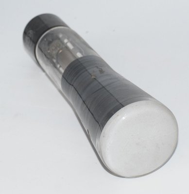
The RCA 902 is a high-vacuum cathode-ray tube (CRT) designed for oscillographic and waveform observation applications. Released by RCA (Radio Corporation of America) with an RMA release number of 399 dated February 21, 1945, the 902 was developed as a compact, portable-friendly CRT suitable for use in test equipment, portable oscilloscopes, and photographic recording of transient and recurrent phenomena.
The 902 features a 2-inch diameter fluorescent viewing screen and employs electrostatic focusing and electrostatic deflection — two pairs of deflecting electrodes positioned at right angles to each other within the bulb neck. This all-electrostatic design eliminated the need for deflection coils or focusing magnets, making the tube ideal for compact, lightweight instruments. The 902 was designed to operate with anode voltages as low as 400 volts, and it could electrically replace the earlier RCA-913 provided the anode No. 2 voltage was not less than 400 volts.
As a product of the wartime and immediate post-war era, the 902 served engineers, radio servicemen, radio amateurs, and school laboratories. Its low cost, small size, and ability to operate at relatively low voltages made cathode-ray oscillography accessible to a much broader audience than had previously been possible with larger, more expensive CRT instruments.
Technical Specifications and Design
General Characteristics
| Parameter | Value |
| Heater Voltage (A.C. or D.C.) | 6.3 ±10% Volts |
| Heater Current | 0.6 Ampere |
| Focusing Method | Electrostatic |
| Deflection Method | Electrostatic |
| Phosphor | No. 1 |
| Fluorescence | Green |
| Persistence | Medium |
| Screen Diameter | 2 inches |
| Minimum Useful Screen Diameter | 1–3/4 inches |
| Screen Type | Medium-Persistence |
| Overall Length | 7-7/16" ±3/16" |
| Greatest Diameter of Bulb | 2" ±1/16" |
| Base | Medium Shell Octal 8-pin |
Electrode Arrangement
The 902 features two sets of electrostatic deflecting electrodes:
- DJ1 and DJ2: Nearest to screen; DJ1 is on the same side of the tube as base pin 3
- DJ3 and DJ4: Nearest to base (electron gun end); DJ3 is on the same side of the tube as base pin 1
Direct Interelectrode Capacitances (Approximate)
| Electrodes | Capacitance |
| Grid No.1 to All Other Electrodes | 7 µµf |
| DJ1 to All Other Electrodes | 9.5 µµf |
| DJ4 to All Other Electrodes | 5.5 µµf |
Maximum Ratings and Typical Operating Conditions
Maximum Ratings Are Absolute Values
| Parameter | Value |
| Anode No. 2 (High-Voltage Electrode) Voltage | 660 max. Volts |
| Anode No. 1 (Focusing Electrode) Voltage | 330 max. Volts |
| Grid No. 1 (Control Electrode) Voltage Range | 0 (never +) to −125 max. Volts |
| Peak Voltage Between Anode No. 2 and Any Deflecting Electrode | 385 max. Volts |
| Impedance of Any Deflecting-Electrode Circuit at Heater-Supply Frequency | 1 max. Megohm |
| Grid-Circuit Resistance | 5 max. Megohms |
Typical Operating Conditions
| Parameter | Typical | Max/Notes |
| Anode No. 2 Voltage* | 400 | 600 Volts |
| Anode No. 1 Voltage for Focus | Approx. 75% of Grid Voltage for cut-off, varied for focus** | |
| Grid Voltage for Cut-Off (Approx.) | 100 | 150 Volts |
| Grid Voltage for Cut-Off‡ | −40 | −60 Volts |
* Brilliance and definition decrease with decreasing anode No. 2 voltages. In general, anode No. 2 voltage should not be less than 400 volts.
** Individual tubes may require between +20% and −35% of values shown for focus when grid No. 1 voltage is varied between zero and cut-off.
‡ Visual extinction of a stationary focused spot. Supply should be adjustable to ±50% of the values shown.
Deflection Sensitivity
| Deflection Plates | Sensitivity (mm/volt D.C.) |
| DJ1 and DJ2 | 0.182 |
| DJ3 and DJ4 | 0.214 |
Deflection Factor‡‡
| Deflection Plates | Factor |
| DJ1 and DJ2 | 93 (139 volts DC/in.) |
| DJ3 and DJ4 | 78 (117 volts DC/in.) |
‡‡ Individual tubes may vary ±20% of the values shown.
Pin-Out (Bottom View of Socket Connections)
| Pin | Connection |
| Pin 1 | G2P2 / DJ3 (Grid No. 2 / Anode No. 2 / Deflecting Electrode 3) |
| Pin 2 | H (Heater) |
| Pin 3 | P1 (Anode No. 1 / Focusing Electrode) |
| Pin 4 | DJ1 (Deflecting Electrode 1) |
| Pin 5 | G1 (Grid No. 1 / Control Electrode) |
| Pin 6 | DJ4 (Deflecting Electrode 4) |
| Pin 7 | H (Heater) |
| Pin 8 | NC (No Connection) |
| K (internal) | Cathode (connected within the tube to one side of the heater; terminal is base pin No. 2) |
The base pins of the 902 fit the standard octal socket. The socket should preferably be mounted so that the tube can be rotated through a small angle for alignment purposes. Insulating baffles between socket contacts provide an additional factor of safety given the high voltages involved.
Physical Construction
The bulb of the 902 is enclosed in a grounded metal case, except for the screen surface. An iron or steel case is employed to minimize the effects of extraneous magnetic fields on tube operation. Care must be taken in construction to ensure the case is completely demagnetized. The cathode is connected within the tube to one side of the heater, with the common connection being base pin No. 2.
Applications and Usage
The RCA 902 was designed primarily as an instrument tube for cathode-ray oscillography. Its principal applications include:
- Portable Oscilloscopes: The compact 2-inch screen and low operating voltages made the 902 ideal for portable oscillographic equipment. The tube's small size and weight contributed to truly portable test instruments.
- Waveform Observation: Study of wave shapes, comparison of frequencies, and measurement of modulation and peak voltages.
- Radio Service and Alignment: Location and adjustment of faults in radio receivers, and indication of balance in bridge circuits.
- Transient Photography: The medium-persistence P1 green phosphor provided good visual and photographic qualities, making the 902 suitable for photographing transient and recurrent phenomena. Orthochromatic film with high green sensitivity was recommended.
- Educational and Laboratory Use: School laboratories and amateur radio operators used the 902 extensively due to its low cost and ease of implementation.
The datasheet provides a complete oscillograph circuit design using the 902 with linear sweep and amplifiers, including a Type 884 thyratron for the sawtooth sweep generator, Type 6J7 voltage amplifiers, and a Type 80 rectifier for the power supply. The circuit operates from a +450V high-voltage supply (point A) and a +200V supply (point C), with the 902's heater powered at +6.5V (point B).
Safety Considerations
The RCA datasheet prominently warns: "The high voltages at which the 902 is operated are very dangerous." Great care must be taken in apparatus design to prevent operator contact with high voltages. All circuit parts at high potentials must be enclosed with interlock switches. Before touching any part of the circuit, the power-supply switch should be turned off and both terminals of any charged condensers grounded. It is also noted that "high voltages may appear at normally low-potential points in the circuit because of condenser breakdown or incorrect circuit connections."
Sound Characteristics
The RCA 902 is a cathode-ray tube (CRT), not an amplifying vacuum tube (triode, pentode, etc.). As such, it does not process audio signals in the traditional sense and has no inherent "sound characteristics" in the way that audio tubes like the 12AX7, 6L6, or 300B do. The 902 does not amplify, rectify, or otherwise shape audio waveforms — it is a display device that converts electrical signals into a visible trace on a phosphorescent screen.
That said, the 902 has an indirect relationship to audio quality assessment: as the heart of early oscilloscopes, it was the primary tool by which engineers and technicians visualized audio waveforms, distortion, frequency response, and transient behavior. The quality of an amplifier's sound could be correlated with what was seen on the 902's green phosphor screen — clipping, crossover distortion, ringing, and other artifacts were made visible. In this sense, the 902 was instrumental in the development and refinement of high-fidelity audio equipment, even though it produced no sound itself.
Equivalent or Substitute Types
The RCA 902 is a specialized cathode-ray tube, and direct equivalents are limited:
- RCA 913: The 902 was designed to electrically replace the RCA-913, provided the anode No. 2 voltage is not less than 400 volts. The 913 is an earlier 1-inch CRT with similar electrostatic deflection architecture. The 902 offers a larger 2-inch screen and improved performance.
- 902-A: Some manufacturers produced variants designated 902-A with minor improvements or tighter specifications. Compatibility should be verified against the specific manufacturer's datasheet.
Due to the specialized nature of CRTs — with specific phosphor types, deflection sensitivities, pin configurations, and voltage requirements — substitution should be approached with caution. The 902's medium-shell octal 8-pin base, P1 green phosphor, and specific deflection factors mean that any substitute must match these parameters for proper operation in existing oscillograph circuits.
Note: The 902 should not be confused with audio amplifier tubes that may share similar numerical designations in other numbering systems. The 902 is exclusively a cathode-ray tube.
Notable Characteristics
- Electrostatic Focus and Deflection: The all-electrostatic design requires no magnets or coils, reducing weight and complexity. Focus is controlled by adjusting the ratio of anode No. 1 voltage to anode No. 2 voltage.
- P1 Green Phosphor: The No. 1 phosphor produces a green fluorescence with medium persistence, offering good visual observation qualities and excellent photographic characteristics. The green hue is well-suited to the peak sensitivity of orthochromatic photographic emulsions.
- Low Operating Voltage: With a typical anode No. 2 voltage of only 400 volts (maximum 660 volts), the 902 operates at significantly lower voltages than many contemporary CRTs, simplifying power supply design.
- Compact Form Factor: At only 7-7/16" overall length with a 2" bulb diameter, the 902 enabled truly portable oscillographic instruments — a significant advancement for field service work.
- Spot Quality: The undeflected focused spot falls within a 10mm square centered at the geometric center of the tube face, with one side parallel to the trace produced by DJ3 and DJ4. Suitable test conditions specify anode No. 2 at 600 volts, anode No. 1 adjusted for focus, and deflecting-electrode resistors of 1 megohm each connected to anode No. 2.
- Screen Burn Protection: The datasheet warns that a high-intensity spot will burn the fluorescent screen if allowed to remain stationary. The beam should be kept in motion or the brilliance reduced via grid voltage adjustment.
- Magnetic Shielding: The iron or steel case surrounding the bulb (except for the screen) provides essential shielding from extraneous magnetic fields, which would otherwise distort the electron beam path and degrade trace accuracy.
- D-C Electrode Coupling: The d-c potential of each deflecting electrode must be maintained essentially equivalent to that of anode No. 2, achieved by connecting resistors of no greater than 10 megohms between each deflecting electrode and anode No. 2. This arrangement minimizes pattern distortion and drift.
Usage in the Audio Community
While the RCA 902 is not an audio tube per se, it holds a meaningful place in the audio community's history and, to a lesser extent, its present:
Historical Significance
The 902 was the CRT at the heart of many early oscilloscopes used by audio engineers, amplifier designers, and hi-fi enthusiasts from the mid-1940s onward. Before the advent of affordable commercial oscilloscopes from companies like Tektronix and Hewlett-Packard, many engineers and hobbyists built their own oscilloscopes around tubes like the 902. The complete oscillograph circuit published in the RCA datasheet — with its sweep generator, vertical and horizontal amplifiers, and calibrated controls — became a widely-copied reference design.
Audio pioneers used 902-based oscilloscopes to:
- Visualize amplifier distortion and clipping behavior
- Measure frequency response using swept signals
- Observe loudspeaker crossover network performance
- Align FM tuners and radio receivers
- Photograph transient response characteristics
Vintage Test Equipment Collecting
Today, the 902 is sought after primarily by collectors of vintage electronic test equipment and by restorers of early oscilloscopes. Instruments built around the 902 — including homebrew oscilloscopes constructed from magazine articles in publications like Radio-Craft, QST, and Electronics — are prized collectibles. A working 902-based oscilloscope represents a tangible connection to the golden age of vacuum tube electronics.
Educational and Demonstration Use
Some audio enthusiasts and educators use vintage CRT oscilloscopes (including those based on the 902 or similar tubes) as demonstration pieces, showing how audio waveforms appear on a classic green phosphor screen. The warm, analog glow of a P1 phosphor trace has an aesthetic appeal that digital oscilloscopes cannot replicate, and these vintage instruments are sometimes displayed alongside tube amplifiers at audio shows and in listening rooms as functional art.
Availability and Condition
The 902 is no longer manufactured and is available only as new-old-stock (NOS) or used/pulled units. As with all CRTs, the phosphor screen degrades over time, particularly if the tube has been operated with a stationary high-intensity spot. Testing a 902 requires specialized equipment — a standard tube tester cannot evaluate CRT performance. Buyers should be aware that condition verification is difficult, and many surviving examples may have reduced phosphor brightness or other age-related degradation.