1. Introduction and History
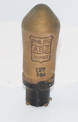
The Philips AB2 is a duo-diode (double diode) vacuum tube manufactured by Philips under their Miniwatt brand, introduced in 1935. It was designed as an improved successor to the earlier AB1 duo-diode, which had been such a complete success that Philips retained the type in their new series with only minor design modifications.
The key improvement of the AB2 over its predecessor was a change in the physical construction: both diodes were now brought out downward through the base pins, eliminating the need for a shielded top-cap connection to the bulb as was required on the AB1. This simplified circuit wiring and improved shielding in receiver designs. The AB2 also featured a quick-heating cathode (Schnellheizkathode) and was noted for its remarkably small physical dimensions.
The AB2 was part of Philips' European "A" series of 4-volt indirectly heated tubes, designed primarily for use in AC-powered radio receivers of the mid-1930s. It belongs to the generation of specialized function tubes that were common in the pre-war European radio industry, where manufacturers like Philips, Telefunken, and Mullard produced dedicated detector and AGC diode tubes rather than relying solely on multi-function combination tubes.
The tube was manufactured with the Philips side-contact base, a proprietary European base system that was common in Philips receiver designs of that era.
2. Technical Specifications and Design
Heater Ratings
| Parameter | Symbol | Value |
|---|---|---|
| Heater Voltage | Vf | 4.0 V |
| Heater Current | If | approx. 0.65 A |
Maximum Ratings and Operating Limits
| Parameter | Symbol | Value |
|---|---|---|
| Maximum Peak Signal Voltage per Diode | — | 200 V (peak) |
| Maximum Rectified Diode Current per Anode | — | 0.8 mA |
| Maximum Resistance between Cathode and Heater | Rfk | 20,000 Ω |
| Maximum Voltage between Cathode and Heater | Vfk max | 125 V |
Note: The 200 V peak signal limit applies to the total peak voltage at either diode anode, including both the carrier wave peak voltage and the modulation increase. The maximum rectified DC diode current must not exceed 0.8 mA per anode.
Note on cathode resistor: When the cathode resistance is less than 1,000 Ω, the decoupling capacitor must be at least 0.1 µF. For higher cathode resistances, a minimum of 1 µF is required.
Tube Classification
The AB2 is a pure duo-diode — it contains no amplifying section (no triode or pentode). It has two independent diode sections (designated d1 and d2) sharing a common indirectly heated cathode. As a diode-only tube, parameters such as amplification factor (µ), transconductance (gm), and plate resistance (rp) are not applicable.
Physical Construction
- Base Type: Philips side-contact base (proprietary European side-contact socket)
- Envelope: Small glass bulb (ST-type miniature envelope), noted for its exceptionally small dimensions
- Overall Width: Approximately 24 mm at the base
- Overall Height: Approximately 81 mm (including base and envelope, based on dimensional drawing — value should be confirmed against original datasheet)
- Cathode Type: Indirectly heated, quick-heating (Schnellheizkathode)
Pin Configuration (Base View)
Based on the Philips datasheet socket diagram (Abb. 3), the side-contact base connections are:
- k — Cathode
- f, f — Filament/Heater (two pins)
- m.k — Metal coating / Cathode connection
- d1 — Diode 1 anode (closest to the pinch/base, used preferably for delayed AGC)
- d2 — Diode 2 anode (furthest from the pinch, used preferably for signal rectification/detection)
The diode designated d2 (furthest from the pinch) is recommended for signal detection/rectification, while d1 (closest to the pinch) is recommended for delayed automatic volume control (AVC/AGC).
3. Applications and Usage
The Philips AB2 was designed for use in AM radio receivers of the 1930s, serving several key functions:
Signal Detection (Demodulation)
The primary application of the AB2 was as an AM detector (demodulator). One of the two diode sections (preferably d2) was used to rectify the intermediate frequency (IF) signal to recover the audio modulation. The advantage of using a dedicated diode detector — as opposed to grid-leak or anode-bend detection in an amplifying tube — was purely linear rectification, which provided superior audio quality even on weak signals.
Automatic Volume Control (AVC / AGC)
The second diode section (preferably d1) was used to generate a delayed automatic volume control (delayed AVC) voltage. This DC voltage, derived from the signal strength, was fed back to the IF and RF amplifier stages to control their gain, maintaining a relatively constant audio output level as signal strength varied. The "delayed" aspect meant that AVC action only began above a certain signal threshold, allowing full sensitivity on weak stations.
Quiet Tuning (Squelch)
The second diode could alternatively be used for quiet tuning (Lautlose Abstimmung), a form of inter-station muting or squelch that silenced the receiver while tuning between stations.
Push-Pull Detection
Both diodes could be used together in a push-pull (Gegentaktschaltung) detection configuration for full-wave rectification of the signal, though the datasheet notes this was of limited practical benefit. More commonly, both diodes were simply connected in parallel for improved detection performance, or one was left unused.
Typical Circuit Configuration
The Philips datasheet (Abb. 5) shows a reference circuit with the AB2 duo-diode feeding a subsequent audio frequency amplifier stage using an AF7 pentode, with delayed automatic volume control. The circuit uses 0.5 MΩ diode load resistors, 200 pF coupling capacitors, a 1.5 MΩ AVC filter resistor, and a 25 µF cathode bypass capacitor on the AF7. The AB2 could also be placed before a triode such as the AC2 for audio amplification.
4. Sound Characteristics
As a pure diode detector, the AB2 does not amplify the signal and therefore does not impart the same kind of tonal coloration that amplifying tubes (triodes, pentodes) are known for. However, the quality of the detection stage has a significant and often underappreciated impact on the overall sound of a vintage radio receiver:
- Linear Detection: The AB2's diode detection provides inherently linear rectification of the AM envelope, which was a marked improvement over the grid-leak and anode-bend detection methods used in earlier receivers. This linearity translates to lower distortion on the recovered audio signal, particularly on weak stations where non-linear detection methods would introduce significant harmonic distortion.
- Clean, Transparent Recovery: Audiophiles who restore and listen to vintage 1930s receivers note that sets using dedicated duo-diode detectors like the AB2 tend to produce a cleaner, more transparent audio signal compared to receivers using combined detector-amplifier tubes where compromises in the detection circuit are inevitable.
- Low Noise Contribution: Because the AB2 is a passive rectifying element (no gain), it contributes minimal additional noise to the signal chain. The quick-heating cathode also helps minimize hum pickup from the heater supply.
- Smooth AGC Action: The delayed AVC function, when properly implemented with the AB2, provides smooth, graceful gain riding that avoids the pumping and breathing artifacts that can occur with poorly designed AGC systems. This contributes to a more pleasant listening experience when tuning across stations of varying strength.
- Warm, Natural Tonality: In the context of a complete vintage receiver, the AB2's contribution to the overall sound is best described as natural and uncolored — it faithfully passes the detected audio to the subsequent amplifier stage, allowing the character of the amplifying tubes (such as the AF7 pentode or AC2 triode) to define the tonal signature.
It should be noted that the "sound" of any detector diode is heavily dependent on the surrounding circuit — load resistor values, filter capacitor sizes, and the impedance matching to the subsequent audio stage all play critical roles in determining the bandwidth, transient response, and overall tonal character of the recovered audio.
5. Equivalent or Substitute Types
The AB2 is a specialized Philips type using the proprietary Philips side-contact base, which significantly limits direct substitution options. The following types are related:
| Type | Relationship | Notes |
|---|---|---|
| AB1 | Direct predecessor | Earlier Philips duo-diode with top-cap connection for one diode. Functionally similar but different physical construction. Not a direct pin-for-pin substitute due to the top-cap difference. |
| EB4 | Similar function, different heater | Philips duo-diode for 6.3V heater series. Same function but different heater voltage — not interchangeable. |
Important: Due to the proprietary Philips side-contact base and the 4.0V heater voltage, there are very few genuinely interchangeable substitutes for the AB2 from other manufacturers. Collectors and restorers of vintage Philips receivers typically need to source original AB2 tubes or NOS (New Old Stock) equivalents. Any substitution attempt should be verified against the specific receiver's schematic and socket wiring. If readers are aware of additional confirmed equivalents, these should be verified against manufacturer cross-reference documentation.
6. Notable Characteristics
- Exceptionally Compact Design: The AB2 was noted by Philips for its remarkably small physical dimensions — it is one of the smallest tubes in the 1935 Philips Miniwatt lineup, reflecting advances in manufacturing precision.
- Quick-Heating Cathode: The Schnellheizkathode (quick-heating cathode) allowed the AB2 to reach operating temperature rapidly, reducing warm-up time for the detection and AGC functions in the receiver.
- Downward-Facing Diode Connections: Unlike the AB1, both diode anodes are brought out through the base pins, eliminating the need for a shielded top-cap wire. This was a significant practical improvement for chassis wiring and shielding.
- Dual-Purpose Diode Sections: The two diode sections are intentionally positioned at different distances from the base to optimize their respective functions — d2 (furthest from base) for signal detection, d1 (nearest to base) for delayed AVC — minimizing interaction between the two functions.
- High Cathode-Heater Voltage Rating: The 125V maximum cathode-to-heater voltage allows the AB2 to be used in circuits where the cathode is elevated significantly above the heater potential, providing design flexibility.
- Philips Side-Contact Base: This proprietary base system, while elegant in design, means the AB2 can only be used in equipment designed for this specific socket type.
- Historical Significance: The AB2 represents the mid-1930s philosophy of using dedicated, optimized tubes for each function in a receiver, before the trend toward multi-function combination tubes (such as the later duo-diode-triodes and duo-diode-pentodes) became dominant.
7. Usage in the Audio Community
The Philips AB2 occupies a niche position in the audio community, primarily among vintage radio restoration enthusiasts and collectors of pre-war European radio equipment:
Vintage Radio Restoration
The AB2 is most commonly encountered in original Philips radio receivers from the mid-to-late 1930s. Restorers of these sets — which are prized for their Art Deco cabinetry and sophisticated circuit design — need functioning AB2 tubes to maintain originality. The tube is essential for proper operation of the detection and AGC circuits in these receivers. A weak or failed AB2 will result in poor detection, distorted audio, and malfunctioning automatic volume control.
NOS Collecting
As a relatively obscure pre-war European type, NOS (New Old Stock) AB2 tubes are collectible items. They appear occasionally at European radio swap meets (Börsen), on specialized vintage tube dealer websites, and on auction platforms. Tubes with intact Philips Miniwatt branding and original boxes command premium prices among collectors. The small, elegant glass envelope with the Philips Miniwatt shield logo makes them visually distinctive display pieces.
Limited Modern Audio Use
Unlike popular audio tubes such as the ECC83, EL34, or 300B, the AB2 sees virtually no use in modern audio amplifier designs. This is because:
- It is a pure diode with no amplification capability
- The proprietary Philips side-contact base is not supported by modern tube socket manufacturers
- Its function (AM detection and AGC) is not relevant to modern audio amplifier or preamplifier design
- Supply is extremely limited and the tubes are irreplaceable once depleted
Educational and Historical Interest
The AB2 is of interest to radio historians and educators as an example of the specialized tube types that were common in the golden age of European radio. It illustrates the design philosophy of the 1930s, where each tube in a receiver was optimized for a specific function, and demonstrates the evolution from the AB1 to the improved AB2 design. The accompanying Philips application circuits (showing the AB2 with AF7 pentode audio amplifier and delayed AVC) are excellent teaching examples of classic superheterodyne receiver design principles.
Sourcing and Availability
The AB2 is a rare tube on the current market. Restorers seeking replacements should check specialized European vintage tube dealers, particularly those in the Netherlands, Germany, and Belgium where Philips equipment was most prevalent. Testing should be performed with a tube tester capable of accommodating the Philips side-contact base, or by measuring diode forward conductance in-circuit.