1. Introduction and History
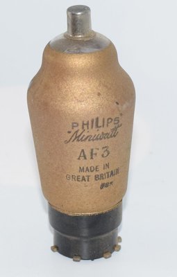
The Philips AF3 is a variable-mu (remote cutoff) high-frequency pentode introduced in 1935 under the Philips Miniwatt brand. Officially designated as an H.F.-Penthode-Selektode (High-Frequency Pentode Selectode), the AF3 was designed as a direct replacement for the earlier AF2, offering significant improvements in AGC (Automatic Gain Control) performance and cross-modulation characteristics.
The key innovation of the AF3 was its completely exponential transfer characteristic, which allowed smooth volume control without distortion or cross-modulation — a persistent problem in earlier variable-mu designs. Philips marketed this tube specifically for use in superheterodyne receivers of the mid-1930s, where it served as an RF amplifier or IF (intermediate frequency) amplifier stage with automatic or manual gain control.
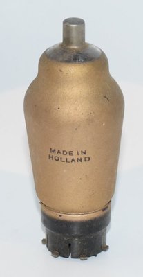
The AF3 belongs to the European 4-volt indirectly heated valve family, using the standard side-contact base common to Philips tubes of this era. It was manufactured primarily by Philips in the Netherlands and was also available through Philips' subsidiary brands. The tube carries the military/CV designation CV2833.
With its 1935 datasheet publication date, the AF3 represents a mature point in pre-war European valve design, where manufacturers had refined the variable-mu pentode concept to achieve excellent RF performance with minimal spurious effects.
2. Technical Specifications and Design
Electrical Ratings (from Philips Miniwatt Datasheet, 1935)
| Parameter | Symbol | Value |
|---|---|---|
| Heater Voltage | Vf | 4.0 V |
| Heater Current | If | ca. 0.65 A |
| Anode Voltage | Va | 250 V |
| Screen Grid Voltage | Vg2 | 100 V |
| Anode Current (at Vg1 = ca. −3 V) | Ia | 8 mA |
| Anode Current (at Vg1 = −55 V) | Ia | ≤ 0.015 mA |
| Screen Grid Current (at Ia = 8 mA) | Ig2 | 2.6 mA |
| Maximum Transconductance | S max | 2.8 mA/V |
| Normal Transconductance (at Ia = 8 mA) | S norm | 1.8 mA/V |
| Transconductance (at Vg1 = −55 V) | S | ≤ 0.002 mA/V |
| Internal Resistance (at Ia = 8 mA) | Ri norm | 1.2 MΩ |
| Internal Resistance (at Vg1 = −55 V) | Ri | ≥ 10 MΩ |
| Maximum Grid Resistance (grid circuit) | Rg1 max | 2.5 MΩ * |
| Max Resistance between Cathode and Heater | Rfk max | 20,000 Ω ** |
| Max Voltage between Heater and Cathode | Vfk max | 80 V |
| Grid-to-Anode Capacitance | Cag1 | ≤ 0.003 µµF (3 fF) |
* With automatic control of negative bias voltage.
** With a cathode resistor of less than 1000 Ω, the decoupling capacitor must be at least 0.1 µF; with a larger resistor, at least 1 µF.
Additional Operating Data at Reduced Screen Voltage
The datasheet provides alternative operating points at reduced screen grid voltages:
- At Vg2 = 85 V: AGC range from −2 V to −45 V (with S ≤ 0.002 mA/V). Normal transconductance is 2.1 mA/V and normal anode current is 7.5 mA.
- At Vg2 = 60 V: AGC range from approximately −2 V to −35 V. Normal transconductance is 1.5 mA/V and normal anode current is 4 mA.
Reducing the screen grid voltage shortens the AGC control range but allows faster, more aggressive gain control action without significantly reducing sensitivity — a useful trade-off in areas with strong local transmitters.
Physical Characteristics
- Tube Type: Variable-mu (remote cutoff) RF pentode
- Envelope: Glass ST-type (shoulder) envelope
- Base: European side-contact base (Philips type)
- Overall Dimensions: Approximately 43 mm diameter × 106 mm total height (28.7 mm bulb width at widest point above base; 30 mm base diameter)
- Electrode Structure: Five electrodes — cathode (k), control grid (g1), screen grid (g2), suppressor grid (g3), anode (a), plus heater filament (f, f) and metallization (m)
Pin Configuration (Base View)
The AF3 uses a side-contact base with the following pin assignments (as shown in the Philips datasheet, Abb. 2):
- k — Cathode
- f, f — Heater (filament)
- g1 — Control Grid
- g2 — Screen Grid
- g3 — Suppressor Grid
- a — Anode (Plate)
- m — Metallization (internal shield)
The top cap connection carries the anode, with the base pins arranged in the standard Philips side-contact configuration as illustrated in the original datasheet diagram.
Maximum Plate Dissipation
Note: The maximum plate dissipation (Wa max) is not explicitly stated in the available datasheet pages. At the rated operating point of Va = 250 V and Ia = 8 mA, the plate dissipation is 2.0 W. The actual maximum rating should be confirmed against a complete manufacturer datasheet, but is likely in the range of 2.5–3 W based on comparable Philips pentodes of this era.
Amplification Factor (µ)
The amplification factor is not directly stated in the datasheet. However, it can be estimated from the relationship µ = S × Ri. At the normal operating point: µ ≈ 1.8 mA/V × 1.2 MΩ = approximately 2,160. This very high µ is typical of sharp-cutoff and variable-mu RF pentodes of this period.
3. Applications and Usage
The AF3 was designed for two primary applications in superheterodyne radio receivers:
RF (High-Frequency) Amplifier
As a front-end RF amplifier, the AF3 excelled due to its extremely low grid-to-anode capacitance (≤ 0.003 µµF), which minimized feedback and ensured stable operation at high frequencies. The datasheet notes that even at shortwave frequencies down to 12 meters, the tube's input and output damping remained high relative to typical tuned circuit impedances, allowing useful gain at these wavelengths.
For HF amplifier service with manual volume control, Philips recommended the following circuit values: R1 = 25,000 Ω, R2 = 30,000 Ω, R3 = 16,000 Ω, and R4 = 250 Ω.
IF (Intermediate Frequency) Amplifier
The AF3 was equally well-suited as an IF amplifier stage with AGC. The exponential transfer characteristic ensured that gain reduction via AGC bias did not introduce cross-modulation or distortion artifacts — a critical requirement for high-quality reception.
For IF amplifier service with automatic volume control, the recommended circuit used: Vb = 250 V, screen grid voltage of 100 V, R1 = 30,000 Ω, and R2 = 25,000 Ω.
Screen Grid Feed Considerations
An important application note from the datasheet: when using the AF3 as an HF or IF amplifier, the screen grid should preferably be fed through a potentiometer divider rather than a simple series dropping resistor. This prevents the AGC action from being diminished by screen current variations that would otherwise cause the screen voltage to change as the bias is varied.
AGC Control Range
The variable-mu characteristic provides an exceptionally wide AGC control range:
- At Vg2 = 100 V: transconductance varies from 2.8 mA/V (maximum) down to ≤ 0.002 mA/V — a ratio of over 1,400:1
- At Vg2 = 85 V: control range from −2 V to −45 V bias
- At Vg2 = 60 V: control range from −2 V to −35 V bias
4. Sound Characteristics
The Philips AF3, being an RF/IF pentode rather than an audio amplifier tube, was not originally designed for audio signal amplification. However, its sonic characteristics are relevant in the context of vintage radio reception quality and the occasional experimental audio use:
In Its Intended RF/IF Role
The AF3's exponential transfer characteristic was specifically engineered to eliminate the cross-modulation distortion and modulation hum that plagued earlier variable-mu designs like the AF2. In practical terms, this meant that radio receivers using the AF3 delivered noticeably cleaner audio, particularly when AGC was actively adjusting gain. Listeners noted smoother volume transitions when tuning between stations of different strengths, without the "pumping" or distortion artifacts common with cruder variable-mu tubes.
The very high internal resistance (1.2 MΩ) contributes to excellent signal isolation and minimal loading of tuned circuits, which translates to better selectivity and therefore cleaner separation of adjacent stations — an audible benefit in crowded broadcast bands.
Tonal Qualities in Experimental Audio Use
When experimenters have used RF pentodes like the AF3 in audio voltage amplifier stages, the results tend to exhibit characteristics common to high-impedance pentodes: a bright, detailed, and somewhat forward presentation. The very high plate resistance means that the tube's gain is highly dependent on the load impedance, and without careful circuit design, the frequency response can be uneven. The low transconductance compared to dedicated audio pentodes means that gain per stage is modest unless high-impedance loads are used.
The 4-volt heater and side-contact base make the AF3 impractical for most modern audio applications, and its sonic character in audio circuits is more of historical curiosity than practical interest. In its proper RF role, the AF3 contributes to the warm, rich, and slightly rolled-off high-frequency character that is the hallmark of well-designed 1930s superheterodyne receivers — a sound that many vintage radio enthusiasts find deeply appealing.
5. Equivalent or Substitute Types
| Type | Relationship | Notes |
|---|---|---|
| CV2833 | Direct equivalent (military designation) | Identical tube with British military CV numbering. Direct drop-in replacement. |
| AF2 | Predecessor | Earlier Philips variable-mu pentode. The AF3 replaced the AF2 with improved exponential characteristic and better cross-modulation performance. Not a direct substitute — the AF3 offers superior AGC behavior. |
Important Note: The AF3 uses the European 4-volt side-contact base, which is specific to the Philips/European valve ecosystem of the 1930s. There is no direct American octal or loctal equivalent with identical pinout. Tubes such as the 6K7 (American variable-mu RF pentode) serve a similar circuit function but use completely different bases, heater voltages, and operating parameters, and are not pin-compatible substitutes.
Builders restoring vintage European receivers requiring the AF3 should seek NOS (New Old Stock) AF3 or CV2833 tubes, as there are no modern production equivalents.
6. Notable Characteristics
- True Exponential Transfer Curve: The AF3's most significant technical achievement was its fully exponential Ia/Vg1 characteristic. This was a deliberate improvement over the AF2 and ensured that AGC action produced proportional gain reduction without introducing nonlinear distortion products.
- Exceptionally Low Grid-Anode Capacitance: At ≤ 0.003 µµF (3 femtofarads), the AF3 offered outstanding isolation between input and output, enabling stable high-gain operation at frequencies well into the shortwave bands without neutralization.
- Very High Internal Resistance: The 1.2 MΩ plate resistance at the normal operating point (rising to ≥ 10 MΩ at cutoff) is characteristic of a well-designed RF pentode, ensuring minimal damping of tuned anode circuits and maximum voltage gain.
- Wide AGC Range: The transconductance ratio of over 1,400:1 (from 2.8 mA/V maximum down to ≤ 0.002 mA/V) provided an AGC control range exceeding 60 dB — impressive for a 1935 design.
- Favorable Cross-Modulation Factor: The datasheet specifically highlights the AF3's advantageous cross-modulation factor (Quermodulationsfaktor), which was a key selling point over competing variable-mu pentodes.
- Shortwave Capability: Philips noted that the AF3 delivered excellent performance even at 12 meters (25 MHz), which was remarkable for a general-purpose RF pentode of the mid-1930s.
- Metallized Envelope: The internal metallization (connected to pin 'm') provided electrostatic shielding, reducing pickup of stray fields and improving stage-to-stage isolation in multi-tube receivers.
7. Usage in the Audio Community
The Philips AF3 occupies a niche position in the audio community, valued primarily by vintage radio restoration enthusiasts rather than by audiophiles building high-fidelity amplifiers.
Vintage Radio Restoration
The AF3 is most commonly encountered in European superheterodyne receivers from the mid-to-late 1930s, particularly those manufactured by Philips and its associated brands. Restorers of these radios prize working AF3 tubes because they are essential to maintaining the original circuit design and performance characteristics. A receiver designed around the AF3's specific AGC curve will not perform optimally with substitute tubes that have different transfer characteristics.
Collectors of Philips Miniwatt tubes appreciate the AF3 for its elegant construction and the distinctive Philips side-contact base. The tube's glass envelope and internal electrode structure are representative of the high manufacturing standards Philips maintained during this period.
Limited Modern Audio Application
The AF3 sees virtually no use in modern audio amplifier construction for several practical reasons:
- The 4.0 V heater voltage is non-standard for modern designs (which typically use 6.3 V or 12.6 V heater supplies)
- The side-contact base requires specialized sockets that are difficult to source
- As an RF pentode, its characteristics are not optimized for audio frequency amplification
- The tube is relatively scarce and commands collector prices that make it uneconomical for audio experimentation
Collector and Historical Interest
Within the tube collecting community, the AF3 is valued as a representative example of 1930s Philips engineering. The "Selectode" branding — Philips' proprietary term for their variable-mu pentode range — is a recognized mark of quality among European valve collectors. AVO-tested examples (verified on the classic AVO valve tester) command premium prices, as confirmed working tubes become increasingly scarce.
The AF3 also holds historical significance as a tube that helped establish the superheterodyne receiver as the dominant radio architecture in Europe during the 1930s. Its refined AGC performance made possible the kind of effortless, distortion-free listening that convinced consumers to upgrade from simpler TRF (Tuned Radio Frequency) receivers to the more complex but superior superheterodyne design.
For those interested in the evolution of vacuum tube technology, the AF3 represents an important milestone in the development of variable-mu pentodes — the point at which manufacturers achieved truly exponential transfer characteristics, solving the cross-modulation problem that had limited earlier designs.