1. Introduction and History
The Philips AK2 is an octode (eight-electrode) mixer tube introduced in 1935 as part of the Philips Miniwatt range. It was designed as an improved successor to the earlier AK1 mixing octode, incorporating several significant engineering advances that reflected the rapid evolution of superheterodyne receiver technology in the mid-1930s.
The name "Oktode" (octode) directly indicates the tube's electrode count: in addition to the cathode and anode, six grids are built into the structure. Conceptually, the AK2 can be understood as two sections layered one upon the other — a triode oscillator section and an HF pentode mixer section — combined within a single glass envelope. This elegant integration allowed a single tube to perform both local oscillator generation and frequency mixing (conversion), a critical function in superheterodyne radio receivers.
The AK2 represented a new generation of Philips Miniwatt tubes featuring the P-base (side-contact base), a quick-heating cathode (Schnellheizkathode), and a solid anode (Vollanode) replacing the earlier gauze anode used in the AK1. These improvements resulted in reduced socket losses, faster warm-up times, smaller physical dimensions, and significantly better performance on shortwave bands — the AK2 was documented to work flawlessly at wavelengths as short as 15 meters, with satisfactory results even at 7 meters.
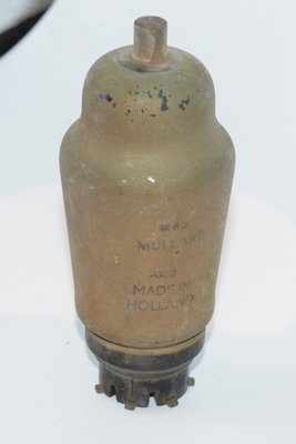
The tube was manufactured by Philips in Holland and also produced under the Mullard brand in the UK, reflecting the close relationship between these companies within the Philips group. It was widely used in European radio receivers of the mid-to-late 1930s.
2. Technical Specifications and Design
Electrode Structure
The AK2 contains eight electrodes arranged as follows (numbered from cathode to anode):
- Cathode (k) — Indirectly heated, quick-heating type
- Grid 1 (g1) — Oscillator control grid (first grid of the triode section)
- Grid 2 (g2) — Oscillator anode (auxiliary anode of the triode section)
- Grid 3 (g3) — Screen grid (shields the triode section from the pentode section)
- Grid 4 (g4) — Signal input grid (control grid of the mixer/pentode section)
- Grid 5 (g5) — Screen grid of the pentode section
- Grid 6 (g6) — Suppressor grid (internally connected to cathode)
- Anode (a) — Solid anode (Vollanode)
The triode section (g1 + g2) generates the local oscillator signal. The screen grid g3 provides electrostatic shielding between the oscillator and mixer sections. The upper portion of the tube (g4, g5, g6, anode) functions as an HF pentode with a virtual cathode formed between g3 and g4. The electron stream is first modulated by the oscillator and then further modulated by the incoming signal on g4, producing the intermediate frequency (IF) output at the anode.
Electrical Ratings (from Philips Miniwatt Datasheet, 1935)
| Parameter | Symbol | Value |
|---|---|---|
| Heater Voltage | Vf | 4 V |
| Heater Current | If | approx. 0.65 A |
| Anode Voltage | Va | 250 V |
| Auxiliary Anode Voltage (Oscillator Anode, g2) | Vg2 | 90 V (max) |
| Screen Grid Voltage (g3 and g5) | Vg3,5 | 70 V |
| Negative Grid Bias (g4, non-oscillating) | Vg4 | approx. −1.5 V |
| Anode Current (at Vg4 ≈ −1.5 V) | Ia | 1.6 mA1 |
| Screen Grid Current (g3 + g5) | Ig3+5 | 3.8 mA1 |
| Oscillator Anode Current (g2) | Ig2 | 2 mA1 |
| Conversion Transconductance (at Ia = 1.6 mA) | Sc | 0.6 mA/V1 |
| Conversion Transconductance (at Vg4 = −25 V) | Sc | ≤ 0.002 mA/V1 |
| Internal Resistance (at Ia = 1.6 mA) | Ri | 1.6 MΩ1 |
| Internal Resistance (at Vg4 = −25 V) | Ri | ≥ 10 MΩ1 |
| Max. Grid Circuit Resistance (g4) | Rg4 max | ≥ 2.5 MΩ |
| Max. Resistance Cathode–Heater | Rfk max | 5000 Ω2 |
| Max. Voltage Heater–Cathode | Vfk | 50 V |
| Capacitance Grid 4 to Anode | Cag4 | ≤ 0.06 µµF |
1 Oscillator voltage on g1 approximately 8.5 V.
2 With a cathode resistance of 1000 Ω, the decoupling capacitor must be at least 0.1 µF; with a larger resistance, at least 1 µF.
Recommended Operating Resistor Values
The DC voltages of the various electrodes with respect to the cathode, and the associated dropping resistor values from a common supply, are specified as follows:
| Electrode | Voltage | Va = 200 V | Va = 250 V |
|---|---|---|---|
| Grid 1 (g1) | −1.5 V* | (bias via grid leak resistor) | |
| Grid 2 (g2, max) | 90 V | R4 = 12,500 Ω | R4 = 12,500 Ω |
| Grids 3 and 5 | 70 V | R5 = 2,000 Ω | R5 = 2,000 Ω |
| Grid 4 | −1.5 V | R6 = 10,000 Ω | R6 = 14,000 Ω |
* In non-oscillating condition. In the oscillating state, the grid bias on g1 is approximately −9 V, developed automatically through a 50,000 Ω grid leak resistor. An oscillator voltage of approximately 8.5 V AC is required across the oscillator circuit.
Physical Characteristics
- Base Type: P-base (Philips side-contact base), also known as the "Philips P" socket
- Envelope: Glass envelope (ST-type shape), compact dimensions
- Overall Dimensions: Approximately 46 mm diameter × 116 mm height (from datasheet drawing, Abb. 6)
- Base Diameter: Approximately 35 mm (35.6 mm per drawing)
- Cathode Type: Indirectly heated, quick-heating (Schnellheizkathode)
- Anode Type: Solid anode (Vollanode), replacing the gauze anode of the AK1
- Mounting: Vertical
Pin Configuration (P-Base, Bottom View)
Per the socket diagram (Abb. 5) in the datasheet, the pin assignments on the P-base are:
- k — Cathode
- f, f — Heater (filament) connections
- g1 — Oscillator grid (Grid 1)
- g2 — Oscillator anode (Grid 2)
- g3 — Screen grid (Grid 3)
- g4 — Signal grid (Grid 4) — brought out to a top cap
- g5 — Screen grid (Grid 5)
- g6 — Suppressor grid (Grid 6, internally connected to cathode)
- a — Anode
- m — Metallization (screen)
Grid 4 (the signal input grid) is connected to a top cap on the envelope to minimize stray capacitance, achieving the remarkably low grid-to-anode capacitance of ≤ 0.06 pF (µµF).
3. Applications and Usage
The AK2 was designed specifically as a frequency converter (mixer-oscillator) for superheterodyne radio receivers. Its primary application was in the front end of AM broadcast receivers covering medium wave, long wave, and shortwave bands.
Superheterodyne Mixer-Oscillator
In a typical superheterodyne circuit, the AK2 performs two simultaneous functions:
- Local Oscillator: The triode section (g1 and g2) generates a stable local oscillator signal. Grid 1 is coupled via a grid leak resistor and capacitor to the oscillator tuned circuit, which feeds back to g2 (the oscillator anode). The feedback is adjusted to produce approximately 8.5 V AC oscillator voltage, which corresponds to a grid current of about 190 µA through the 50,000 Ω grid leak resistor.
- Mixer: The incoming RF signal is applied to Grid 4 (the signal grid of the pentode section). The electron stream, already modulated by the oscillator, is further modulated by the signal frequency, producing sum and difference frequencies at the anode. The desired intermediate frequency (IF) is selected by the IF transformer connected to the anode circuit.
Shortwave Performance
The AK2 was specifically noted for its excellent shortwave performance. The datasheet states that it works flawlessly at wavelengths as short as 15 meters and produces satisfactory results even at 7 meters. This was a significant improvement over the AK1, attributed to the solid anode construction. For shortwave operation, it was recommended to increase the g2 voltage up to 90 V for better oscillation, while the voltage on g3 and g5 must not exceed 70 V.
AGC (Automatic Gain Control)
The AK2 supports automatic volume control (AVC/AGC) through variation of the bias on Grid 4. The conversion transconductance drops from 0.6 mA/V at the normal operating point (Vg4 = −1.5 V) to ≤ 0.002 mA/V at Vg4 = −25 V, providing an excellent gain control range. Importantly, varying the g4 bias has minimal effect on the oscillator frequency — at 200 m wavelength, a bias change from −1.5 V to −25 V causes only about 300 Hz of frequency shift.
Anti-Frequency-Pulling Circuit
For shortwave use where frequency stability is critical, the datasheet describes a special circuit (Abb. 7) using anode current feedback to compensate for oscillator frequency drift. In this arrangement, the feedback coupling is shared between the oscillator anode current (Ig2) and the main anode current (Ia), achieving near-complete compensation. This technique maintains both oscillator amplitude and frequency stability even as the AGC voltage changes.
Advantages Over Earlier Mixer Tubes
The Philips datasheet lists ten specific advantages of the AK2:
- Input and oscillator circuits are almost completely separated
- High conversion gain due to pentode characteristics of the mixer section
- Gain is independent of anode voltage — practically the same sensitivity at 100 V as at 200 V
- No radiation back into the antenna
- Easy gain control via Grid 4 bias
- Minimal oscillator frequency pulling during AGC operation (only ~300 Hz at 200 m wavelength over the full AGC range)
- Significantly less noise
- Practically no whistles (birdies)
- Reliable operation on shortwave bands
- Non-microphonic
4. Sound Characteristics
It is important to note that the AK2 was designed as a frequency converter tube, not as an audio amplifier. It was never intended to directly process audio signals, and its "sound" in the traditional audiophile sense is not directly applicable in the way one might describe an audio output tube or preamplifier tube. However, the AK2's characteristics do influence the overall sonic quality of the radio receivers in which it was used, and vintage radio enthusiasts have noted several qualities:
Noise Performance
The AK2 was specifically praised by Philips for producing "significantly less noise" ("bedeutend weniger Rauschen") compared to earlier mixer tubes. In a superheterodyne receiver, the mixer stage is one of the primary contributors to the overall noise figure, so a quieter mixer directly translates to a cleaner, more listenable signal with less background hiss. Vintage radio collectors who have compared receivers using the AK2 against those with earlier converter tubes often note the noticeably quieter background.
Freedom from Spurious Signals
The datasheet's claim of "practically no whistles" ("praktisch keine Pfeiftöne") is significant. Mixer tubes can generate unwanted spurious responses — birdies, heterodyne whistles, and image responses — that manifest as annoying tones superimposed on the desired program material. The AK2's superior isolation between oscillator and signal circuits, combined with its pentode mixer section, minimizes these artifacts, resulting in cleaner reception.
Tonal Quality in Vintage Receivers
In the context of vintage radio listening, the AK2 contributes to a warm, smooth reception quality characteristic of well-designed 1930s European superheterodyne receivers. The tube's low conversion noise and freedom from spurious signals allow the full tonal character of the IF amplifier and audio stages to come through without degradation. The non-microphonic nature of the tube also means it does not add mechanical vibration artifacts to the audio.
Shortwave Listening Quality
On shortwave bands, where the AK2 particularly excels, its stable oscillator and low frequency drift contribute to a steady, unwavering tone quality. Frequency drift in a mixer-oscillator can cause the received signal to slowly shift in pitch or fade in and out as it moves off the IF passband — effects that the AK2's design specifically minimizes.
5. Equivalent or Substitute Types
The AK2 is a specialized Philips octode with a P-base (side-contact base), which limits direct substitution options. The following types are related:
| Type | Relationship | Notes |
|---|---|---|
| AK1 | Direct predecessor | Earlier Philips octode mixer. Uses a different base and has a gauze anode instead of the AK2's solid anode. Not pin-compatible. Inferior shortwave performance. |
| EK2 | Electrically similar, different heater | The EK2 is the 6.3 V heater equivalent in the Philips "E" series. It shares the same octode mixer principle but uses a different heater voltage (6.3 V vs. 4 V) and may have different base/pinout. Not a direct drop-in replacement — heater circuit modification required. Confirm pin compatibility before substitution. |
| TK2 | Related type, different heater | The Philips "T" series equivalent with a different heater voltage configuration. Not directly interchangeable without circuit modifications. |
Important: Due to the AK2's use of the Philips P-base (side-contact base) and its specific 4 V heater requirement, there are very few true drop-in replacements. The tube was manufactured by Philips (Holland), Mullard (UK, as part of the Philips group), and possibly other Philips-affiliated manufacturers. When seeking replacements, the safest approach is to source NOS (New Old Stock) AK2 tubes from any of these manufacturers, as they are electrically identical.
There is no direct American (octal or loctal base) equivalent for the AK2, as American octode/converter designs of the same era (such as the 6A8/6A7 pentagrid converter) use fundamentally different electrode arrangements and base types.
6. Notable Characteristics
Innovative Multi-Function Design
The AK2 is a remarkable example of 1930s vacuum tube engineering, combining a triode oscillator and a pentode mixer within a single envelope using eight electrodes. The internal shielding provided by Grid 3 achieves near-complete isolation between the oscillator and signal circuits, resulting in the extremely low grid-4-to-anode capacitance of ≤ 0.06 pF.
Quick-Heating Cathode
The AK2 features a Schnellheizkathode (quick-heating cathode), which was a significant improvement for consumer radio receivers, reducing the warm-up time before the set became operational.
Solid Anode Construction
The transition from the AK1's gauze (mesh) anode to the AK2's solid anode (Vollanode) was a key engineering improvement. The solid anode provides better electrostatic shielding, more consistent performance, and critically, much better operation at high frequencies (shortwave bands). The datasheet specifically attributes the AK2's excellent shortwave performance to this design change.
Exceptional Gain Control Range
The AK2 offers an outstanding AGC range. The conversion transconductance drops from 0.6 mA/V at the normal operating point to ≤ 0.002 mA/V at Vg4 = −25 V — a ratio of at least 300:1, or approximately 50 dB of gain control range. This is achieved with minimal impact on oscillator frequency stability.
High Internal Resistance
The internal resistance of 1.6 MΩ at the normal operating point (rising to ≥ 10 MΩ at cutoff) is characteristic of a pentode-type mixer section and allows efficient coupling to high-impedance IF transformer loads.
Complex Internal Construction
The datasheet includes a photograph (Abb. 3) of the AK2's internal structure with the anode removed, revealing the complex arrangement of six concentric grid structures. This intricate construction was a testament to the precision manufacturing capabilities of Philips in the 1930s.
P-Base Socket
The AK2 uses the Philips P-base (side-contact base), which was designed to minimize dielectric losses in the socket — an important consideration at radio frequencies. This base type, while superior in RF performance, is specific to the European Philips/Mullard ecosystem.
7. Usage in the Audio Community
The AK2's role in the audio community is primarily within the vintage radio restoration and collecting hobby rather than in modern audio amplifier construction. Its significance can be understood in several contexts:
Vintage Radio Restoration
The AK2 is an essential component for the authentic restoration of mid-to-late 1930s European superheterodyne radio receivers, particularly those manufactured by Philips and brands that used Philips/Mullard tubes. Collectors and restorers of these vintage sets actively seek NOS (New Old Stock) AK2 tubes to maintain originality and proper operation. A radio with a weak or failed AK2 will have poor sensitivity, excessive noise, or no reception at all, as the mixer-oscillator is the heart of the superheterodyne front end.
Shortwave Listening (SWL) Enthusiasts
The AK2's documented excellent shortwave performance makes vintage receivers equipped with this tube attractive to shortwave listening enthusiasts who appreciate the character of tube-based reception. The tube's low noise, stable oscillator, and freedom from spurious responses contribute to a pleasant listening experience on the shortwave bands, even by modern standards.
Historical and Educational Interest
The AK2 is studied by tube enthusiasts and electronics historians as an excellent example of the sophisticated multi-electrode tube designs that emerged in the 1930s. The octode concept — combining oscillator and mixer functions in a single tube with effective internal shielding — represents a high point in vacuum tube engineering for radio frequency applications. Educational demonstrations of superheterodyne principles often reference tubes like the AK2.
Not Used in Modern Audio Amplifier Construction
Unlike many other vintage tubes that have found new life in modern hi-fi amplifiers, guitar amplifiers, or headphone amplifiers, the AK2 is not typically used in contemporary audio circuit design. There are several reasons for this:
- It is a frequency converter tube, not designed for audio amplification
- The P-base socket is uncommon and difficult to source
- The 4 V heater voltage is non-standard for modern builds
- NOS stock is limited and primarily reserved for vintage radio restoration
- Its electrical characteristics (very high internal resistance, low transconductance in mixer mode) are not well-suited to audio amplification
Collectibility
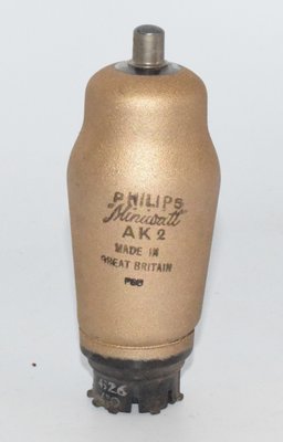
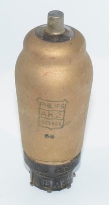
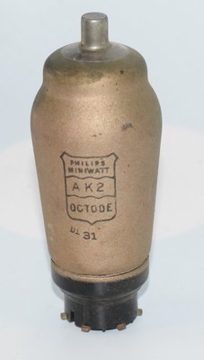
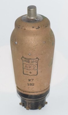
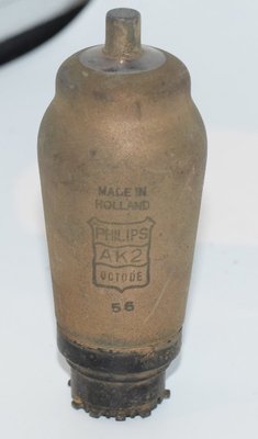
AK2 tubes, particularly those with original Philips Miniwatt branding, are collectible items. Tubes manufactured by Philips Holland, Mullard Holland, and Philips UK have all been documented in the marketplace. Collectors value tubes that test well on AVO or similar valve testers, as the complex multi-grid structure of octodes can be prone to inter-electrode shorts or emission degradation with age. The distinctive appearance of the tube — with its compact ST-shaped glass envelope, side-contact P-base, and top cap for the signal grid — makes it an attractive display piece for tube collections.