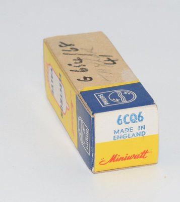
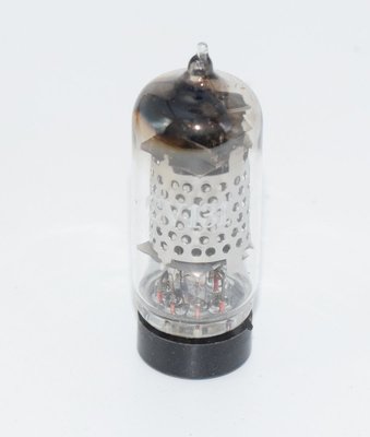
Introduction and History
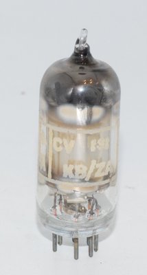
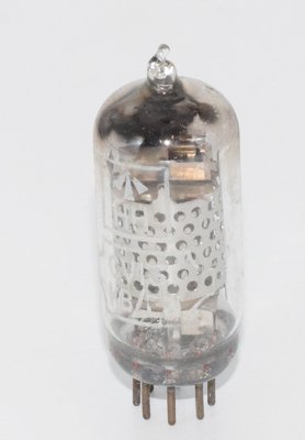
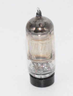
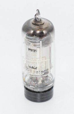
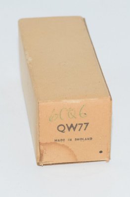
The CV131 is the British military CV (Common Valve) designation for the well-known EF92 / W77 variable-mu (remote cutoff) radio-frequency pentode. Registered under the RTMA system as the 6065 (its American equivalent designation), this miniature valve was developed in the late 1940s and formally registered on May 28, 1951, as documented in RTMA release #977. The CV131 was manufactured by several prominent British firms, including the M-O Valve Company (MOV/GEC), Brimar (Standard Telephones and Cables Limited, Footscray, Kent), and Thorn AEI, among others.
The CV prefix denotes that this valve was qualified and approved for use in British military and government equipment, where stringent quality control, reliability under adverse conditions, and tight parameter tolerances were mandatory. The CV131 was designed specifically for trustworthy operation under adverse conditions of vibration and mechanical shock — a critical requirement for military radio receivers, radar IF strips, and airborne communications equipment deployed during the Cold War era.
As a variable-mu (remote cutoff) pentode, the CV131 was primarily intended for use in the R.F. (radio frequency) and I.F. (intermediate frequency) amplifier stages of compact radio equipment, where automatic gain control (AGC) was required. Its miniature B7G glass envelope made it ideal for the increasingly compact equipment designs of the post-war period, replacing earlier octal-based equivalents.
Pre-1957 examples from the M-O Valve Company are particularly sought after by collectors and audio enthusiasts, as these early production runs are reputed to exhibit superior construction quality and tighter manufacturing tolerances characteristic of the MOV Hammersmith and Wembley factories.
Technical Specifications and Design
Mechanical Data
| Cathode Type | Coated unipotential (indirectly heated) |
| Base | Miniature glass button 7-pin (B7G / E7-1) |
| Basing Number | 7DB |
| Bulb / Envelope | T-5½ |
| Maximum Diameter | ¾ inch (19 mm) |
| Maximum Overall Length | 2⅛ inches (54 mm) |
| Maximum Seated Height | 1⅞ inches (48 mm) |
| Mounting Position | Any |
| Maximum Shock (intermittent) | 500 g |
| Vibration (continuous service) | 2½ g |
| Mechanical Resonance | None below 100 c/s |
Pin Connections (B7G Base, Bottom View)
| Pin | Connection |
|---|---|
| Pin 1 | Grid No. 1 (Control Grid) |
| Pin 2 | Cathode (and internal shield) |
| Pin 3 | Heater |
| Pin 4 | Heater |
| Pin 5 | Plate (Anode) |
| Pin 6 | Grid No. 3 (Suppressor Grid) and internal shield |
| Pin 7 | Grid No. 2 (Screen Grid) |
Note: The external shield, when used, should be connected to Pin 2 (Cathode).
Electrical Ratings (Absolute Maximum)
| Heater Voltage (AC or DC) | 6.3 volts |
| Heater Current | 200 mA (0.2 A) |
| Maximum Heater-Cathode Voltage | 90 volts |
| Maximum Plate Voltage | 250 volts |
| Maximum Grid No. 2 (Screen) Voltage | 250 volts |
| Maximum Plate Dissipation | 2.5 watts |
| Maximum Grid No. 2 Dissipation | 0.6 watt |
Direct Interelectrode Capacitances
| Grid to Plate (Cga, max) | 0.004 pF (with external shield connected to Pin 2) |
| Input: g1 to (h+k+g2+g3+i.s.) | 4.5 pF |
| Output: p to (h+k+g2+g3+i.s.) | 7.0 pF |
The extraordinarily low grid-to-plate capacitance of just 0.004 pF (4 fF) is a hallmark of this design, achieved through careful internal shielding. This makes the CV131 exceptionally stable in RF amplifier service, virtually eliminating feedback between output and input circuits.
Typical Operating Conditions — Class A1 Amplifier
Two sets of typical operating conditions are provided in the manufacturer datasheet:
| Parameter | Condition 1 | Condition 2 |
|---|---|---|
| Heater Voltage | 6.3 V | 6.3 V |
| Heater Current | 200 mA | 200 mA |
| Plate Voltage | 250 V | 250 V |
| Grid No. 3 (Suppressor) Voltage | 0 V | 0 V |
| Grid No. 2 (Screen) Voltage | 150 V | 200 V |
| Grid No. 1 (Control Grid) Voltage | −0.65 V | −2.5 V |
| Plate Resistance (approx.) | 1.0 MΩ | 1.0 MΩ |
| Transconductance (gm) | 2,500 µmhos (2.5 mA/V) | 2,500 µmhos (2.5 mA/V) |
| Plate Current | 8.0 mA | 8.0 mA |
| Grid No. 2 Current | 2.0 mA | 2.1 mA |
The amplification factor (µ) can be derived from the relationship µ = gm × rp. With gm = 2,500 µmhos (0.0025 S) and rp = 1.0 MΩ (1,000,000 Ω), the amplification factor µ ≈ 2,500. This very high µ is characteristic of sharp-cutoff and variable-mu RF pentodes of this era, though in practice the usable stage gain is determined by the load impedance and circuit configuration.
Applications and Usage
The CV131 was designed and specified for the following primary applications:
- RF Amplifier Stages: The extremely low grid-to-plate capacitance (0.004 pF) and high plate resistance (1.0 MΩ) make the CV131 ideal for stable, high-gain RF amplification in receivers operating from medium wave through VHF frequencies.
- IF Amplifier Stages: The variable-mu (remote cutoff) characteristic allows smooth AGC (Automatic Gain Control) action, making it a natural choice for IF strips in superheterodyne receivers where signal levels vary widely.
- Military Communications Receivers: The CV131 designation indicates qualification for British military service. Its robust construction — withstanding 500 g shock and 2½ g continuous vibration with no mechanical resonance below 100 c/s — made it suitable for airborne, shipboard, and vehicular radio equipment.
- Radar IF Strips: Multiple CV131 stages were commonly cascaded in radar intermediate frequency amplifier chains, where the combination of high gain, excellent shielding, and AGC capability was essential.
- Test Equipment: The valve's stable characteristics and tight CV-specification tolerances made it popular in laboratory-grade signal generators, spectrum analyzers, and measurement receivers.
- Audio Preamplification: Although not its original design intent, the CV131/EF92 has found widespread secondary use as a low-level audio voltage amplifier, particularly in microphone preamplifiers and phono stages, where its high gain and relatively low noise floor are advantageous.
Sound Characteristics
The CV131/EF92, when employed in audio circuits, has developed a devoted following among audiophiles and recording engineers. Its sonic character is frequently described in the following terms:
- Rich, Warm Midrange: The CV131 is widely praised for a lush, harmonically rich midrange that imparts a sense of body and warmth to vocals and acoustic instruments. This warmth is often attributed to the tube's relatively high transconductance and the gentle, even-order harmonic distortion profile typical of well-designed pentode stages.
- Smooth, Non-Fatiguing Treble: Unlike some sharper-sounding miniature pentodes, the CV131 tends to produce a treble that is detailed but never harsh or strident. The high-frequency roll-off is gentle and musical, making it forgiving of bright source material.
- Excellent Low-Level Detail: With its high gain (µ ≈ 2,500) and low noise floor — particularly in selected military-grade CV131 examples — this valve excels at resolving subtle musical details, micro-dynamics, and ambient information in recordings.
- Slightly Soft Bass: Some users note that the bass response, while tuneful and well-defined, lacks the absolute tightness and slam of triode-based designs. This is a common characteristic of pentode voltage amplifier stages and can be mitigated through careful circuit design and power supply regulation.
- "Vintage" Character: The overall sonic signature is often described as having a distinctly vintage, "BBC" quality — unsurprising given that the EF92 family was extensively used in BBC broadcast equipment. This character is particularly pronounced in pre-1957 M-O Valve Company examples, which are said to offer a slightly more refined and three-dimensional soundstage compared to later production.
- Pentode vs. Triode-Strapped Operation: When triode-strapped (screen grid tied to plate), the CV131 takes on a different character — lower gain but with reduced output impedance, lower distortion, and a more linear, transparent sound. Many audio designers offer switchable pentode/triode operation to allow users to choose between the richer pentode voicing and the cleaner triode presentation.
It should be noted that sonic impressions are inherently subjective and heavily dependent on the surrounding circuit topology, passive component quality, power supply design, and the specific manufacturer and production era of the individual valve.
Equivalent and Substitute Types
Close / Identical Substitutes (Direct Drop-In Replacements)
| Type | Notes |
|---|---|
| 9D6 | Identical electrically and physically; direct drop-in replacement for the CV131. |
| EF92 | The Mullard/Philips Pro-Electron designation for the same valve. The CV131 is the CV-registered version of the EF92. Fully interchangeable. |
| W77 | The M-O Valve Company (MOV/GEC) proprietary designation for the same type. Fully interchangeable with CV131/EF92. |
Different Rating Substitutes (NOT Direct Drop-In)
| Type | Notes |
|---|---|
| 6065 | The American RTMA/EIA designation. While based on the same fundamental design and sharing the same datasheet (as per the attached Brimar document), the 6065 may have slightly different selection criteria or tolerances compared to the CV131 military specification. Generally usable as a substitute but may not meet the tighter CV131 parametric limits. Check bias points carefully. |
| CV4015 | A different CV-number designation that is related but NOT a guaranteed drop-in replacement. The CV4015 may have different screening criteria, tighter tolerances, or slightly different operating parameters. Substitution should be verified against the specific equipment's requirements. |
Important: While the EF92, W77, and 9D6 are generally considered identical to the CV131, the 6065 and CV4015 should be treated as related types that may require circuit verification before substitution. Always confirm bias conditions and operating points when substituting between these types.
Notable Characteristics
- Variable-Mu (Remote Cutoff) Design: The CV131's control grid is wound with variable pitch, creating a remote-cutoff characteristic. This means that as the negative grid bias is increased, the tube's transconductance decreases gradually rather than cutting off abruptly. This is essential for smooth AGC operation in receiver circuits and also contributes to the tube's graceful overload behavior in audio applications.
- Exceptional Internal Shielding: The grid-to-plate capacitance of just 0.004 pF (specified as maximum with external shield connected to cathode at Pin 2) is remarkably low, even by the standards of dedicated RF pentodes. This is achieved through careful internal shield construction connected to Pin 6 (along with the suppressor grid) and Pin 2 (cathode).
- Military-Grade Ruggedness: The CV131 specification demands survival of 500 g intermittent shock and 2½ g continuous vibration, with no mechanical resonance below 100 c/s. This makes it one of the more robust miniature pentodes available, and contributes to its reputation for long service life and reliability.
- High Plate Resistance: The approximately 1.0 MΩ plate resistance is characteristic of pentode operation and means that the tube behaves as a near-ideal current source. This has implications for audio circuit design — the tube works best with high-impedance loads or with careful impedance matching.
- Low Heater Power: At 6.3 V and only 200 mA (1.26 W heater dissipation), the CV131 is relatively economical in terms of heater power, making it practical for battery-operated or portable equipment — one of its original design goals.
- Manufacturer Variations: CV131 valves from different manufacturers (M-O Valve Co., Brimar, Thorn AEI, Mullard, etc.) can exhibit subtle differences in construction, internal geometry, and sonic character despite meeting the same CV specification. Pre-1957 M-O Valve Company examples are particularly prized by collectors and audio enthusiasts for their perceived superior quality.
Usage in the Audio Community
Despite being designed as an RF/IF amplifier valve, the CV131/EF92 has carved out a significant niche in the audio world, particularly since the revival of interest in valve audio equipment from the 1990s onward.
Microphone Preamplifiers
The CV131 is perhaps most famous in audio circles for its use in classic microphone preamplifier designs. The valve's high gain, low noise, and musical distortion characteristics make it well-suited to amplifying the tiny signals from dynamic and ribbon microphones. Several boutique microphone preamplifier manufacturers have built their reputations around circuits featuring the EF92/CV131, and the valve appears in numerous DIY preamplifier projects popular in the recording community.
Phono Stages
The high gain available from the CV131 in pentode mode makes it attractive for phono preamplifier (RIAA) stages, where the very low output of moving-coil and moving-magnet cartridges demands substantial amplification. The tube's low grid-to-plate capacitance also helps maintain bandwidth and high-frequency accuracy in these demanding applications.
Headphone Amplifiers
Several commercial and DIY headphone amplifier designs employ the CV131/EF92 as a voltage amplifier stage, typically driving a cathode follower or output transformer. The tube's rich harmonic character is considered particularly complementary to headphone listening, where the intimate presentation reveals the valve's tonal qualities.
Guitar Amplifiers
While less common than the ubiquitous 12AX7/ECC83 in guitar amplifier service, the CV131/EF92 has been used in some boutique and custom guitar amplifier designs, particularly in preamp stages where its high gain and variable-mu characteristic provide a distinctive overdrive character — smooth and gradual rather than abrupt.
Vintage Equipment Restoration
The CV131 remains in demand for the restoration and maintenance of vintage British communications receivers, BBC broadcast equipment, and military radio sets from the 1950s and 1960s. The availability of NOS (New Old Stock) CV131 valves from various manufacturers ensures that these historically significant pieces of equipment can be kept in operational condition.
Collector and NOS Market
In the NOS valve market, CV131 examples are graded and priced according to manufacturer, production era, and measured parameters. The hierarchy of desirability generally places pre-1957 M-O Valve Company (MOV) production at the top, followed by early Brimar and Mullard examples. Thorn AEI production is also well-regarded. Matched pairs and quads command premium prices for use in stereo and multi-channel audio equipment. The military CV131 designation itself carries a premium over commercially-marked EF92 equivalents, as the CV specification implies tighter quality control and parameter selection.
Practical Considerations for Audio Use
Audio designers working with the CV131 should note several practical considerations:
- The 1.0 MΩ plate resistance in pentode mode demands careful load matching — plate load resistors of 100 kΩ to 470 kΩ are typical in audio circuits.
- Triode-strapping (connecting Pin 7/screen to Pin 5/plate) dramatically reduces gain but lowers output impedance and distortion, and is preferred by some designers for line-level applications.
- The suppressor grid (Pin 6) should be connected to cathode (Pin 2) in most audio applications, as per the standard operating conditions.
- Screen grid supply regulation is important for low-noise performance — a well-filtered, low-impedance screen supply significantly reduces hum and noise.
- The internal shield connection to Pin 2 means that proper grounding of the cathode circuit is essential for achieving the specified low capacitance and noise performance.