Introduction and History
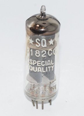
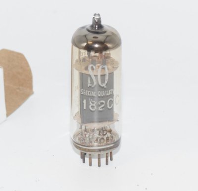
The E182CC is a Special Quality (SQ) double triode manufactured by Philips, first documented in tentative data sheets dated July 7, 1958. Designated under Philips' prestigious SQ program — which denoted tubes manufactured to enhanced reliability and tighter tolerances — the E182CC was specifically designed for use in computer circuits (counting and switching applications). The tube carries the Philips document number 938 3159 and was produced primarily at the Philips Heerlen factory in Holland.
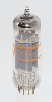
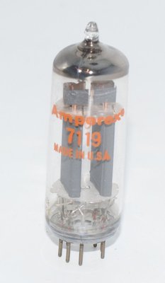
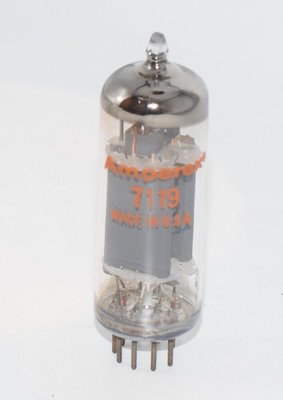
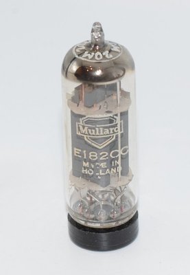
The "E" prefix in the European Pro-Electron naming convention indicates a 6.3V heater voltage, while "CC" denotes a special quality double triode with separate cathodes. The tube is also known by its American RETMA designation 7119 and its British military CV number CV5766. Mullard-branded examples were also manufactured at the Philips Heerlen facility, typically during the 1960s.
The E182CC was engineered to maintain its emission capabilities after long periods of operation under cut-off conditions — a critical requirement for computer switching circuits where tubes might remain in a non-conducting state for extended periods. However, the datasheet explicitly states that it is not intended to be used in circuits critical as to hum, microphony or noise. This is an important distinction that separates it from audio-oriented special quality types like the E88CC or E188CC.
Despite its computer-circuit origins, the E182CC has found a devoted following in the audio community due to its robust construction, high transconductance, substantial current-handling capability, and the exceptional build quality inherent in Philips SQ production. Early production examples, particularly the sought-after "pinched glass" variants from 1959, command premium prices among collectors and audiophiles.
Technical Specifications and Design
General Description
| Type | Special Quality Double Triode with separate cathodes |
| Intended Application | Computer circuits (counting/switching) |
| Base | Noval (9-pin) |
| Envelope | Glass miniature, max diameter 22 mm |
| Overall Height | Max 60.3 mm (seated), max 66.7 mm (total) |
| Mounting | Any position |
Heater Data
| Parameter | 6.3V Operation | 12.6V Operation |
|---|---|---|
| Heater Voltage (Vf) | 6.3 V | 12.6 V |
| Heater Current (If) | 640 mA | 320 mA |
| Heater Pins | 8–(4+5) parallel | 4–5 series |
Heating is indirect, by AC or DC, with parallel supply. Heater voltage tolerance is ±5%. For 6.3V operation, pins 4 and 5 are connected together and the heater is fed between this junction and pin 8. For 12.6V series operation, the heater is connected between pins 4 and 5. The characteristic range for heater current at 6.3V is 605–675 mA.
Pin Configuration (Noval Base, Bottom View)
| Pin | Function |
|---|---|
| 1 | Anode' (a') — Section 2 |
| 2 | Grid' (g') — Section 2 |
| 3 | Cathode' (k') — Section 2 |
| 4 | Heater (f) |
| 5 | Heater (f) |
| 6 | Cathode (k) — Section 1 |
| 7 | Grid (g) — Section 1 |
| 8 | Heater center-tap (fc) |
| 9 | Anode (a) — Section 1 |
Note the separate cathodes on pins 3 and 6 — this is a key design feature enabling independent biasing of each triode section, which was essential for the tube's intended computer switching applications.
Typical Characteristics (Each Triode Section)
| Parameter | Condition 1 | Condition 2 |
|---|---|---|
| Anode Voltage (Va) | 120 V | 150 V |
| Grid Voltage (Vg) | −2 V | −14 V |
| Anode Current (Ia) | 36 mA | max 0.2 mA |
| Transconductance (S) | 15 mA/V | — |
| Amplification Factor (μ) | 24 | — |
From the typical characteristics, the calculated plate resistance (ri) at Va = 120V, Vg = −2V is:
ri = μ / S = 24 / 15 = 1.6 kΩ
The characteristic range values for equipment design at Va = 120V, Vg = −2V show Ia ranging from 26 to 45 mA, and S ranging from 11.2 to 18.8 mA/V. At the end of life (Column III), the minimum acceptable values are Ia = 24 mA and S = 8 mA/V (at Va = 120V, Rk = 55Ω).
Additional Characteristic Data
| Parameter | Conditions | Value |
|---|---|---|
| Anode Current | Va = 90V, Ig = 250 μA | 41–62 mA (range) |
| Anode Current | Va = 120V, Rk = 55Ω | S = 11.2–18.8 mA/V (range) |
| Grid Current (−Ig) | Va = 120V, Vg = −2V, Rg = 0.1 MΩ | <0.2 μA |
| Cathode-Heater Leakage (Ikf) | Vkf = 200V, R = 1 MΩ | <15 μA |
Absolute Maximum Ratings (Each Triode Section)
| Parameter | Symbol | Maximum Value |
|---|---|---|
| Anode Supply Voltage | Vao | 600 V |
| Anode Voltage (DC) | Va | 300 V |
| Anode Dissipation (per section) | Wa | 4.5 W |
| Total Anode Dissipation (both sections) | Wa + Wa' | 8.0 W |
| Grid Current | Ig | 8 mA |
| Grid Current (pulse, 10 μsec, δ=1%) | Igp | 200 mA |
| Negative Grid Voltage | −Vg | 100 V |
| Negative Grid Voltage (pulse, 10 μsec, δ=1%) | −Vgp | 200 V |
| Positive Grid Voltage | +Vg | 1 V |
| Positive Grid Voltage (pulse, 10 μsec, δ=1%) | +Vgp | 30 V |
| Cathode Current | Ik | 60 mA |
| Cathode Current (pulse, 10 μsec, δ=1%) | Ikp | 400 mA |
| Heater-Cathode Voltage (peak) | Vkfp | 200 V |
| Heater Voltage | Vf | 6.3 V ±5% / 12.6 V ±5% |
| Maximum Bulb Temperature | tbulb | 160 °C |
Note: The heater-cathode voltage maximum is 200V peak, with the DC component limited to a maximum of 120V.
Maximum Circuit Limits
| Parameter | Condition | Maximum |
|---|---|---|
| Grid Resistance (Rg) | Automatic (cathode) bias | 1 MΩ |
| Grid Resistance (Rg) | Fixed bias | 0.5 MΩ |
Interelectrode Capacitances
| Capacitance | Typical (Section 1) | Typical (Section 2) | Range |
|---|---|---|---|
| Anode-Grid (Cag / Ca'g') | 3.9 pF | 4.0 pF | 3.4–4.6 pF / 3.4–4.8 pF |
| Anode (Ca / Ca') | 1.1 pF | 1.0 pF | 0.75–1.45 pF / 0.65–1.35 pF |
| Grid (Cg / Cg') | 5.8 pF | 5.8 pF | 5.3–6.7 pF / 5.3–6.7 pF |
| Cathode-Heater (Ckf / Ck'f) | 3.7 pF | 3.7 pF | — |
| Grid-Grid (Cgg') | <0.15 pF | ||
| Anode-Anode (Caa') | 0.6 pF (typ), <0.8 pF (max) | ||
| Anode-Grid cross (Cag' / Ca'g) | <0.1 pF each | ||
Insulation
Insulation resistance between any two electrodes: >100 MΩ (new tube specification), with end-of-life minimum of 20 MΩ.
Life Expectancy
The E182CC is rated for a life expectancy of 5,000 hours under the specified life-test conditions: +150V supply through 62 kΩ and 1.5 kΩ anode resistors, Vf = 6.3V, Vkf = 120V (cathode negative). End-of-life parameters are specified in Column III of the characteristics tables.
Applications and Usage
The E182CC was specifically designed by Philips for use in computer circuits — particularly counting circuits, binary scaling, and switching applications that were fundamental to early digital computing systems of the late 1950s and 1960s. Its key design features that suited it to these applications include:
- Emission retention under cut-off: The tube maintains its emission capabilities after long periods of operation in the cut-off condition, which is essential in flip-flop and counting circuits where one triode section may remain non-conducting for extended periods.
- Separate cathodes: Independent cathode connections for each triode section allow flexible circuit configurations essential for bistable multivibrator (flip-flop) circuits.
- High transconductance (15 mA/V): Enables fast switching with good signal differentiation between on and off states.
- High current capability (36 mA typical, 60 mA max per section): Provides robust drive capability for subsequent stages and indicator circuits.
- High pulse ratings: Peak cathode current of 400 mA and peak grid current of 200 mA (at 10 μsec, 1% duty cycle) accommodate the transient demands of switching circuits.
- High heater-cathode voltage rating (200V peak): Allows stacking of tube circuits in series-connected heater strings common in computer equipment.
- SQ reliability: Tighter manufacturing tolerances and enhanced quality control ensure consistent performance across production lots — critical for large computer installations using hundreds or thousands of identical tubes.
Beyond its original computer application, the E182CC's robust specifications have made it attractive for other demanding applications including:
- Regulated power supply circuits (as a series pass or error amplifier element)
- Cathode follower output stages where high current drive is needed
- Line driver and impedance matching circuits
- Headphone amplifier output stages
- Preamplifier and driver stages in high-end audio equipment
Sound Characteristics
Despite being designed for digital switching rather than audio, the E182CC has earned a strong reputation in the audiophile community for its distinctive sonic qualities. It is important to note that the datasheet explicitly warns the tube is not intended for circuits critical as to hum, microphony, or noise — so careful circuit design and tube selection are necessary when using it in audio applications.
Audiophiles and audio engineers who have used the E182CC in appropriate circuits generally describe its sound as follows:
- Dynamic and authoritative: The high transconductance (15 mA/V) and substantial plate current (36 mA) give the E182CC a sense of effortless power and dynamic headroom that smaller-signal dual triodes cannot match. Transients are rendered with speed and impact.
- Full-bodied midrange: The tube is praised for a rich, dense midrange presentation with excellent tonal weight. Vocals and acoustic instruments are rendered with a satisfying sense of body and presence.
- Extended but controlled bass: The low plate resistance (approximately 1.6 kΩ) provides excellent damping and control, particularly in cathode follower configurations. Bass response is typically described as tight, well-defined, and extended.
- Smooth treble: While not as delicate or airy as some lower-current signal triodes, the E182CC delivers a smooth, grain-free treble that avoids harshness. The relatively high interelectrode capacitances (Cag = 3.9 pF, Cg = 5.8 pF) may gently roll off the extreme high frequencies in some circuit topologies, contributing to a non-fatiguing presentation.
- Excellent current drive: In cathode follower and headphone amplifier applications, the E182CC's ability to deliver substantial current translates to a sense of grip and control over the load, with excellent macro-dynamics.
- Vintage character variations: Early production examples — particularly the prized "pinched glass" variants from 1959 and early Heerlen production with D-getter construction — are often described as having a more open, three-dimensional soundstage compared to later production. However, these subjective differences should be considered in the context of normal production variation.
The E182CC's sonic character is fundamentally different from lower-current dual triodes like the ECC82/12AU7 or ECC83/12AX7. Its high-current, low-impedance nature gives it a more muscular, direct sound that some listeners prefer for driving headphones or as a buffer/driver stage, while others may find it lacks the delicacy of purpose-designed audio tubes in voltage amplifier roles.
Equivalent or Substitute Types
Genuine equivalents and substitutes for the E182CC are limited due to its unusual combination of high transconductance, high current capability, and separate cathodes:
| Type | Relationship | Notes |
|---|---|---|
| 7119 | Direct equivalent (RETMA designation) | American designation for the same tube. Fully interchangeable. |
| CV5766 | Direct equivalent (British military) | British military CV designation for the E182CC. Fully interchangeable. |
Important: Tubes That Are NOT Substitutes
The E182CC is frequently confused with or incorrectly listed as interchangeable with the following types. These are NOT suitable substitutes:
- ECC82 / 12AU7: While sharing the same Noval base and dual triode configuration, the ECC82 has vastly different characteristics: μ ≈ 17, S ≈ 2.2 mA/V, Ia ≈ 10 mA, Wa = 2.75W per section. The E182CC has μ = 24, S = 15 mA/V, Ia = 36 mA, and Wa = 4.5W per section. The E182CC draws nearly seven times the transconductance and over three times the plate current. Substituting one for the other will result in drastically incorrect operating points and potential damage to the circuit or tube.
- ECC81 / 12AT7: Also not interchangeable despite the Noval base. Different operating characteristics and current requirements.
- E88CC / 6922: Different pinout (shared cathode on pin 8 vs. separate cathodes), different heater current, and different operating parameters. Not pin-compatible.
When seeking the E182CC, look specifically for tubes marked E182CC, 7119, or CV5766. There is no widely available modern production equivalent; the tube must be sourced as NOS (New Old Stock) or used/tested vintage stock.
Notable Characteristics
- Exceptional emission longevity under cut-off: The E182CC's defining feature is its ability to maintain emission after prolonged periods in the cut-off state. This was engineered specifically for computer switching circuits but also benefits audio applications where one section may operate at very low current.
- NOT a low-noise/low-microphony tube: Contrary to what might be assumed from its SQ designation, the datasheet explicitly states the E182CC is "not intended to be used in circuits critical as to hum, microphony or noise." The SQ designation here refers to reliability, consistency, and longevity — not low-noise performance. Audio designers should account for this with appropriate circuit topology, shielding, and vibration isolation.
- Very high transconductance for a dual triode: At 15 mA/V, the E182CC has exceptionally high mutual conductance for a medium-mu dual triode, approaching the territory of some power tubes. This gives it excellent gain-bandwidth product and fast response.
- Low plate resistance: The calculated ri of approximately 1.6 kΩ is remarkably low for a small-signal dual triode, making it an excellent candidate for cathode follower circuits where low output impedance is desired.
- High anode dissipation: At 4.5W per section (8.0W total for both sections), the E182CC can handle significantly more power than typical dual triodes, providing substantial headroom in audio circuits.
- Substantial heater power: The 640 mA heater current at 6.3V (approximately 4W total heater power) reflects the tube's robust construction but must be accounted for in power supply design.
- High pulse ratings: Peak cathode current of 400 mA and peak grid voltage ratings of −200V/+30V (pulse) indicate the tube's capability for demanding switching applications.
- Tight section matching: The SQ manufacturing process ensured close matching between the two triode sections, with capacitance values nearly identical between sections (e.g., Cag = 3.9 pF vs. Ca'g' = 4.0 pF). This is beneficial for balanced/differential audio circuits.
- Philips Heerlen production: All known genuine E182CC production originated from the Philips Heerlen factory in Holland, regardless of brand marking (Philips, Mullard, Amperex, etc.). This single-source production ensures consistency across brand variants.
Usage in the Audio Community
The E182CC has carved out a distinctive niche in the high-end audio community, valued precisely for the characteristics that made it excel in computer circuits — high current capability, low output impedance, and robust construction. Its adoption in audio has grown significantly since the early 2000s as designers and enthusiasts explored beyond the conventional audio tube types.
Headphone Amplifiers
Perhaps the most popular audio application for the E182CC is in headphone amplifiers. The tube's low plate resistance (≈1.6 kΩ), high transconductance (15 mA/V), and ability to deliver up to 60 mA cathode current make it exceptionally well-suited for driving headphones directly in cathode follower or White cathode follower configurations. Several boutique headphone amplifier manufacturers have designed products specifically around the E182CC, taking advantage of its ability to drive low-impedance headphones with authority. The tube can comfortably drive headphones from 32Ω to 600Ω with excellent dynamics and control.
Preamplifier and Buffer Stages
Audio designers have employed the E182CC as a high-current buffer or line stage in preamplifiers. Its low output impedance in cathode follower configuration makes it an excellent line driver capable of handling long cable runs and low-impedance loads without signal degradation. The high current capability provides excellent transient response and dynamic headroom.
Driver Stages for Power Amplifiers
The E182CC's combination of moderate gain (μ = 24) and high current drive makes it suitable as a driver stage for power amplifiers, particularly those using larger power tubes that require substantial grid drive current. Its ability to swing significant voltage while delivering current makes it effective in interstage coupling applications.
DAC Output Stages
Some high-end digital-to-analog converter designs use the E182CC as an output buffer following the DAC chip, leveraging its current drive capability and low output impedance to provide a tube-buffered analog output with excellent load-driving ability.
Collectibility and Market
The E182CC has become a sought-after collector's tube, with prices reflecting its scarcity and audio reputation. Key variants in order of desirability include:
- Philips Miniwatt "Pinched Glass" (1959): The earliest production with a distinctive pinched envelope shape. These are the rarest and most expensive, commanding premium prices among collectors.
- Early Heerlen production (late 1950s–early 1960s): D-getter construction, often with Philips Miniwatt or SQ branding. Highly regarded for both sound quality and collectibility.
- Mullard-branded Heerlen production: Manufactured at the same Heerlen factory as Philips-branded examples, typically from the 1960s. These offer identical performance at sometimes lower prices due to brand perception.
- Later Heerlen production (1960s–1970s): O-getter construction, still excellent quality but generally less sought-after than early production.
Design Considerations for Audio Use
Engineers and DIY builders working with the E182CC in audio circuits should keep the following points in mind:
- Microphony: The tube was not designed for low microphony. Use vibration-damping socket mounts and consider tube damper rings. Locate the tube away from transformers and loudspeakers.
- Hum: DC heater supply is strongly recommended for audio applications, as the tube was not optimized for hum rejection with AC heaters.
- Heater current: At 640 mA per tube (6.3V), the heater supply must be adequately rated. Multiple E182CCs will place significant demands on the heater transformer winding.
- Operating point: The typical operating point of Va = 120V, Vg = −2V, Ia = 36 mA provides a good starting point for audio design, but the tube can be operated over a wide range. The plate characteristic curves show useful operation from 50V to over 300V anode voltage.
- Thermal management: With up to 4.5W anode dissipation per section plus 4W heater power, the E182CC generates significant heat. Ensure adequate ventilation and maintain bulb temperature below the 160°C maximum.
- No modern production: All E182CC tubes are vintage NOS or used stock. Test tubes carefully before use, and consider purchasing from reputable dealers who provide test results.