Introduction and History
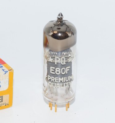
The E80F is a professional-grade reliable pentode manufactured by Philips (and its associated brands including Mullard and Amperex) as part of the prestigious E80-series of "Special Quality" (SQ) vacuum tubes. Introduced in the early 1950s — with the earliest datasheet pages dating to June 6, 1954, and characteristic curves from September 9, 1953 — the E80F was designed specifically for use in professional equipment where exceptional reliability and longevity were paramount.
The Philips datasheet explicitly describes the E80F as a "RELIABLE PENTODE for use in professional equipment (life longer than 10,000 hours)". This designation placed it in the upper echelon of European valve manufacturing, where the "E80" prefix indicated a heater voltage of 6.3V and the "F" suffix denoted a pentode type within the Philips Mullard naming convention. The "SQ" (Special Quality) variant represented even tighter manufacturing tolerances and more rigorous quality control.
The E80-series tubes were developed during a period when broadcasting organizations, telecommunications companies, and scientific instrumentation manufacturers demanded valves that could operate continuously for thousands of hours without significant parameter drift. The E80F fulfilled this need admirably, finding its way into studio equipment, measurement instruments, and high-reliability electronic systems across Europe and beyond. Its American designation is the 6084.
The tube was produced in both standard and SQ (Special Quality) versions, with the SQ variant featuring even tighter parameter tolerances. Both versions were manufactured at the Philips Heerlen factory in the Netherlands, and later by associated factories including Mullard in the United Kingdom.
Technical Specifications and Design
Heater Specifications
| Parameter | Value |
|---|---|
| Heater Voltage (Vf) | 6.3 V |
| Heater Current (If) | 0.3 A |
| Heater Current Tolerance at Vf = 6.3V | ± 0.015 A |
| Heating Method | Indirect, by AC or DC; series or parallel supply |
| Heater Voltage Tolerance (parallel supply) | ± 5% (absolute limits) for 10,000-hour life |
| Heater Voltage Tolerance (series supply) | ± 1.5% (absolute limits) for 10,000-hour life |
Typical Characteristics (at Va = 250V, Vg2 = 100V, Vg3 = 0V)
| Parameter | Symbol | Value |
|---|---|---|
| Anode Voltage | Va | 250 V |
| Suppressor Grid Voltage | Vg3 | 0 V |
| Screen Grid Voltage | Vg2 | 100 V |
| Cathode Resistor | Rk | 550 Ω |
| Anode Current | Ia | 3 ± 0.5 mA |
| Screen Grid Current | Ig2 | 0.65 ± 0.2 mA |
| Transconductance | S | 1.85 ± 0.35 mA/V |
| Internal Resistance | Ri | 1.5 MΩ (min. 1.0 MΩ) |
| Amplification Factor (g2 to g1) | µg2g1 | 25 |
| Equivalent Noise Resistance (f = 0–10 kc/s, Rg1 = 0 Ω) | Req | max. 40 kΩ |
| Grid 1 Reverse Current (Rg1 = 0.1 MΩ) | -Ig1 | max. 0.1 µA |
| Anode Current at Vg1 = -7.5V | Ia | max. 20 µA |
Note: The overall amplification factor µ (anode to control grid) can be calculated as S × Ri = 1.85 mA/V × 1.5 MΩ ≈ 2,775. This high value reflects the very high plate resistance characteristic of this pentode type.
Absolute Maximum Ratings
| Parameter | Symbol | Maximum Value |
|---|---|---|
| Anode Supply Voltage | Vao | 600 V |
| Anode Voltage | Va | 300 V |
| Anode Dissipation | Wa | 1.3 W |
| Screen Grid Supply Voltage | Vg2o | 600 V |
| Screen Grid Voltage | Vg2 | 200 V |
| Screen Grid Dissipation | Wg2 | 0.4 W |
| Negative Suppressor Grid Voltage | -Vg3 | 100 V |
| Negative Control Grid Voltage | -Vg1 | 100 V |
| Maximum Cathode Current | Ik | 9 mA |
| Cathode-Heater Voltage (k pos., f neg.) | Vkf | 120 V |
| Cathode-Heater Voltage (k neg., f pos.) | Vkf | 60 V |
| Cathode-Heater Resistance | Rkf | max. 20 kΩ |
| Heater Voltage | Vf | 6.3 V + 5% (max), 6.3 V - 5% (min) |
| Maximum Bulb Temperature | — | 170 °C |
Interelectrode Capacitances (with external shield)
| Parameter | Symbol | Value |
|---|---|---|
| Anode Capacitance | Ca | 7.3 ± 0.5 pF |
| Grid 1 Capacitance | Cg1 | 5.0 ± 0.5 pF |
| Anode to Grid 1 Capacitance | Cag1 | < 0.025 pF |
| Grid 1 to Heater Capacitance | Cg1f | < 0.002 pF |
| Cathode to Heater Capacitance | Ckf | 3.7 pF |
Hum Voltage
Hum voltage at Vg1 with Rg1 = 1 MΩ: max. 5 µV
Cathode-Heater Insulation
At Vkf = 120 V, the minimum cathode-to-heater resistance Rkf = 10 MΩ.
End-of-Life Criteria
The tube is considered to have reached end of life when one or more of the following conditions are met:
- Ia ≤ 2.0 mA
- Ig2 ≤ 0.35 mA
- S ≤ 1.2 mA/V
- -Ig1 ≥ 0.2 µA
Physical Construction
| Parameter | Value |
|---|---|
| Base Type | Noval (9-pin miniature) |
| Envelope | Glass miniature |
| Maximum Diameter | 22 mm |
| Maximum Overall Height (seated) | 61–67 mm |
| Mounting Position | Any |
Pin Configuration (Noval Base, Bottom View)
Based on the Philips datasheet base diagram:
| Pin | Connection |
|---|---|
| 1 | g3 (Suppressor Grid) / internally connected |
| 2 | g2 (Screen Grid) |
| 3 | k (Cathode) |
| 4 | f (Heater) |
| 5 | f (Heater) |
| 6 | a (Anode) |
| 7 | g1 (Control Grid) |
| 8 | g3 (Suppressor Grid) |
| 9 | s (Internal Shield) |
Note: The datasheet base diagram shows the pin assignments from the bottom view. Pin designations should always be confirmed against the specific manufacturer's datasheet, as the internal shield connection (s) and suppressor grid (g3) connections are critical for proper operation. The suppressor grid appears at both pin 1 and pin 8 in the base diagram.
Shock and Vibration Resistance
The E80F was designed for professional environments and can withstand vibrations of 2.5 g at 50 c/s during 96 hours. It is also proof against impact acceleration of about 500 g, as measured with the N.R.L. impact machine for electronic devices, lifting the hammer over an angle of 30°. This ruggedness was a key selling point for broadcast and industrial applications.
Applications and Usage
The Philips datasheet specifies two primary application areas for the E80F:
1. Resistance-Coupled Audio Frequency Amplifier
The datasheet provides detailed operating characteristics for use as a resistance-coupled AF amplifier with Ra = 0.22 MΩ, Rg1 = 1 MΩ, and Rg1' = 0.68 MΩ. The following operating points are specified:
| Vb (V) | Rg2 (MΩ) | Rk (kΩ) | Ia (mA) | Ig2 (mA) | Vo/Vi | Vo (Veff) | dtot (%) |
|---|---|---|---|---|---|---|---|
| 100 | 1.0 | 3.3 | 0.29 | 0.07 | 120 | 8 | 1.7 |
| 200 | 1.2 | 1.8 | 0.61 | 0.13 | 165 | 20 | 1.6 |
| 250 | 1.2 | 1.5 | 0.80 | 0.17 | 175 | 25 | 1.4 |
| 300 | 1.2 | 1.2 | 0.98 | 0.20 | 190 | 30 | 1.1 |
| 400 | 1.2 | 1.0 | 1.37 | 0.28 | 200 | 40 | 0.9 |
These figures reveal the E80F's remarkable voltage gain capability — achieving gains of 120 to 200 depending on the supply voltage — with very low total distortion figures ranging from 0.9% to 1.7%. The low anode currents (well under the 9 mA maximum cathode current) demonstrate that this is a low-power, high-gain signal tube rather than a power pentode.
2. Electrometer Pentode
The E80F can also be operated as an electrometer pentode at reduced heater voltage. The specified operating conditions for this mode are:
| Parameter | Value |
|---|---|
| Vf | 4.5 V |
| Va | 40 V |
| Vg3 | 0 V |
| Vg2 | 40 V |
| Vg1 | -2.15 V |
| Ia | 40 µA |
| Ig2 | 9 µA |
| Ig1 | < 10⁻¹⁰ A |
The extraordinarily low grid current of less than 10⁻¹⁰ A (0.1 nA) in electrometer mode makes the E80F suitable for precision measurement instruments, pH meters, and other applications requiring extremely high input impedance.
Other Professional Applications
Beyond the two primary applications specified in the datasheet, the E80F found widespread use in:
- Broadcasting equipment: Preamplifiers and line amplifiers in radio and television studios
- Telecommunications: Carrier frequency amplifiers and repeater stations
- Scientific instrumentation: Precision measurement equipment, oscilloscopes, and laboratory instruments
- Recording equipment: Professional tape recorder electronics and disc-cutting amplifiers
- Medical electronics: EEG and ECG amplifier front-ends where low noise and high reliability were essential
Sound Characteristics
The E80F occupies a unique position in the world of audio tubes. Unlike high-transconductance pentodes designed for maximum gain, the E80F operates at very modest current levels with a transconductance of just 1.85 mA/V and an exceptionally high plate resistance of 1.5 MΩ. These characteristics fundamentally shape its sonic signature.
Tonal Qualities
Audiophiles and recording engineers who have worked with the E80F consistently describe the following sonic attributes:
- Exceptional clarity and transparency: The E80F's very low operating currents and high plate resistance contribute to a remarkably clean, transparent sound. There is a sense of "looking through a window" at the music rather than listening through electronics.
- Low noise floor: With an equivalent noise resistance of no more than 40 kΩ and a hum voltage specification of just 5 µV maximum, the E80F provides an exceptionally quiet background. This silence allows micro-details and ambient information to emerge clearly.
- Refined, delicate presentation: The E80F does not have the bold, forward character of higher-transconductance pentodes. Instead, it presents music with a refined, almost ethereal quality that many listeners find captivating for acoustic music, vocals, and chamber ensembles.
- Excellent high-frequency extension: The very low anode-to-grid capacitance (Cag1 < 0.025 pF) and the tube's internal shielding contribute to clean, extended high frequencies without the harshness sometimes associated with pentode operation.
- Natural midrange: When used in well-designed circuits, the E80F produces a midrange that is often described as "liquid" and "natural," with excellent vocal reproduction and instrumental timbre accuracy.
- Controlled, articulate bass: While not a power tube, the E80F's high voltage gain capability and low distortion figures (as low as 0.9% at Vb = 400V) translate to well-defined, articulate bass reproduction in preamplifier stages.
Pentode vs. Triode-Strapped Operation
Some audio designers operate the E80F with the screen grid connected to the anode (triode-strapped), which reduces the plate resistance dramatically and changes the sonic character. In triode mode, the sound becomes warmer and more intimate, though at the cost of significantly reduced gain. In pentode mode, the E80F offers its full voltage gain of up to 200 with the characteristic pentode clarity and detail retrieval.
Comparison to Other Small-Signal Pentodes
Compared to the ubiquitous EF86 (which shares the same Noval base), the E80F is a distinctly different tube. The E80F operates at much lower currents and has a lower transconductance, resulting in a more delicate and refined sound. Where the EF86 can sometimes sound slightly "grainy" in lesser circuits, the E80F's professional-grade construction and tighter tolerances tend to produce a smoother, more composed presentation. The E80F's superior vibration resistance also means less susceptibility to microphonic coloration.
Equivalent or Substitute Types
Confirmed Equivalents
| Designation | Type | Notes |
|---|---|---|
| CV2729 | British Military (NATO) | Close/identical substitute per verified reference data. Direct replacement. |
| 6084 | American (RETMA) | American designation for the E80F. Electrically identical. |
Related but Not Directly Interchangeable Types
| Type | Relationship | Notes |
|---|---|---|
| EF86 / 6267 | Similar application | Also a low-noise AF pentode on Noval base, but with different electrical characteristics (higher transconductance, different operating points). Not a direct substitute — different pinout and operating parameters. |
| EF80 | Same series, different application | An IF/RF pentode from the same E80 reliability series. Different electrical characteristics; not interchangeable. |
| E80F SQ | Premium variant | The Special Quality version of the same tube with tighter parameter tolerances. Fully interchangeable with the standard E80F. |
Note: Some sources list M8212 or CV5215 as equivalents, but these designations are not confirmed in the verified reference data. Users should exercise caution and verify any claimed equivalents against manufacturer documentation before substitution.
Notable Characteristics
Exceptional Longevity
The E80F's defining characteristic is its guaranteed minimum useful life of 10,000 hours — a remarkable specification for the era. To achieve this longevity, Philips specified strict heater voltage tolerances: ± 5% for parallel supply operation and ± 1.5% for series supply operation. The tube's end-of-life is defined by specific parameter degradation thresholds rather than catastrophic failure, ensuring predictable performance throughout its service life.
Very High Plate Resistance
With a typical plate resistance (Ri) of 1.5 MΩ (minimum 1.0 MΩ), the E80F exhibits an exceptionally high output impedance. This characteristic makes it behave almost as a constant-current source, which is advantageous in certain circuit topologies but requires careful attention to load impedance matching. The high Ri, combined with the transconductance of 1.85 mA/V, yields a calculated amplification factor (µ) of approximately 2,775.
Extraordinary Voltage Gain
In resistance-coupled amplifier service, the E80F achieves voltage gains of 120 to 200 depending on operating conditions — remarkable figures for a single amplifier stage. At Vb = 250V with the specified component values, a gain of 175 is achieved with only 1.4% total harmonic distortion and an output voltage of 25 Veff.
Low Operating Currents
The E80F operates at very modest current levels. At the typical operating point (Va = 250V, Vg2 = 100V), the anode current is just 3 mA with a screen current of 0.65 mA, for a total cathode current of approximately 3.65 mA — well within the 9 mA maximum cathode current rating. In the resistance-coupled amplifier configurations, currents are even lower, ranging from 0.29 mA to 1.37 mA depending on supply voltage.
Electrometer Capability
The ability to operate as an electrometer pentode with grid currents below 10⁻¹⁰ A is a testament to the exceptional quality of the E80F's internal construction and vacuum processing. This capability is rare among production tubes and speaks to the precision manufacturing standards applied to the E80F.
Mechanical Robustness
The E80F's ability to withstand 2.5 g vibrations at 50 Hz for 96 hours continuously, and impact accelerations of approximately 500 g, made it suitable for mobile and industrial installations where lesser tubes would fail from microphonic noise or mechanical damage.
Internal Shielding
The E80F features an internal shield (connected to a dedicated pin on the Noval base) in addition to provisions for an external shield. This dual-shielding approach minimizes electromagnetic interference pickup and contributes to the tube's exceptionally low noise performance. The very low grid-to-anode capacitance (Cag1 < 0.025 pF) and grid-to-heater capacitance (Cg1f < 0.002 pF) are direct results of this careful internal shielding design.
Usage in the Audio Community
High-End Preamplifier Designs
The E80F has earned a devoted following among designers of high-end tube preamplifiers. Its combination of very high voltage gain, low noise, and low distortion makes it an attractive choice for phono stages and line-level preamplifiers. The tube's ability to achieve gains of 175 or more in a single stage can simplify circuit topology, potentially reducing the number of gain stages needed and thereby minimizing cumulative distortion and noise.
Phono Stage Applications
The E80F is particularly prized in moving-magnet (MM) and, with appropriate step-up transformers, moving-coil (MC) phono preamplifier designs. Its low equivalent noise resistance (max. 40 kΩ), extremely low hum voltage (max. 5 µV), and high gain make it well-suited to amplifying the tiny signals from phono cartridges. Several boutique amplifier manufacturers have built their flagship phono stages around the E80F.
Microphone Preamplifiers
In the professional recording world, the E80F has been used in microphone preamplifier designs where its low noise, high gain, and professional-grade reliability are essential. Some vintage studio equipment originally designed with the E80F continues to be sought after by recording engineers who value its sonic character.
DAC Output Stages
Some contemporary audio designers have incorporated the E80F into the output stages of digital-to-analog converters, using the tube's natural harmonic characteristics to add warmth and dimensionality to the digital signal path. The tube's high gain allows it to serve as both a gain stage and a buffer in these applications.
Headphone Amplifiers
The E80F has found a niche in high-end headphone amplifier designs, particularly in hybrid configurations where the tube serves as the voltage amplification stage driving a solid-state output buffer. Its refined sonic character and low noise floor are especially appreciated in the intimate listening environment of headphone use.
Collector Market and Availability
The E80F commands premium prices in the collector and audiophile markets. Original Philips Heerlen production (identifiable by specific factory codes and construction details) is the most sought-after, followed by Mullard-manufactured examples. The SQ (Special Quality) variants command the highest prices due to their tighter tolerances and perceived superior sonic performance.
Key factors affecting value include:
- Manufacturing origin: Philips Heerlen (Netherlands) production is most prized
- SQ designation: Special Quality variants command a significant premium
- Date codes: Earlier production runs (1950s) are generally preferred by collectors
- NOS (New Old Stock) condition: Unused, original-boxed examples fetch the highest prices
- Matched pairs/quads: Tubes tested and matched for critical parameters are valued for stereo applications
Circuit Design Considerations for Audio Use
Designers working with the E80F in audio circuits should note several important considerations:
- Maximum cathode current: The 9 mA Ik limit must be respected. The total of anode current plus screen current must not exceed this value.
- Screen grid supply: The screen grid is typically fed through a high-value dropping resistor (1.0–1.2 MΩ per the datasheet's AF amplifier circuit) from the B+ supply, with appropriate bypassing (0.5 µF specified in the datasheet).
- Grid resistor values: The maximum Rg1 value depends on the operating conditions and is detailed in the datasheet's chart (page H), showing how Rg1 max varies with Rk and Rg2 values. At the typical operating point with Rg2 = 0 Ω, Req = max. 40 kΩ.
- Heater-cathode voltage: The generous Vkf rating of 120V (k positive) allows the E80F to be used in circuits with elevated cathode potentials, useful in DC-coupled designs.
- Shielding: For lowest noise, both the internal shield pin and an external tube shield should be properly grounded.
- Vibration isolation: Despite its excellent vibration resistance, socket damping is recommended in the most critical audio applications to minimize any residual microphonic effects.
Community Reputation
Within the audio community, the E80F is regarded as one of the finest small-signal pentodes ever manufactured. Its professional heritage, exceptional build quality, and refined sonic character have earned it a reputation that extends well beyond its original intended applications. Forum discussions and reviews consistently highlight its transparency, low noise, and musical naturalness. The tube represents a pinnacle of European valve manufacturing craftsmanship from the golden age of professional electronics, and its continued popularity among audiophiles and designers is a testament to the enduring quality of Philips' engineering.