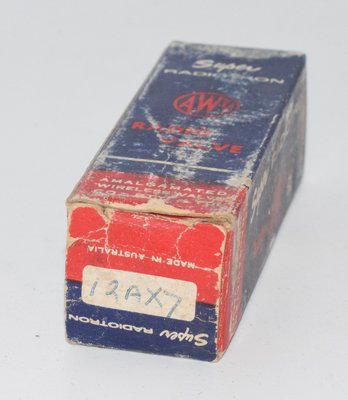
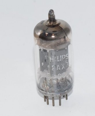
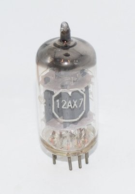
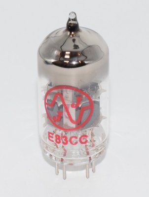
1. Introduction and History
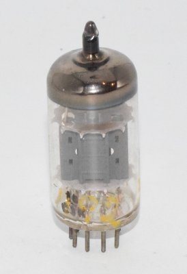
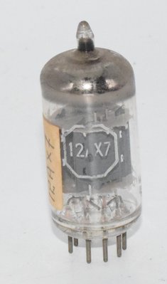
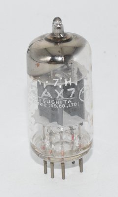
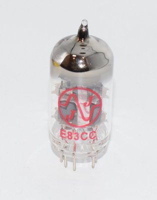
The E83CC is a premium-grade double triode vacuum tube (valve) developed as a high-reliability, low-noise, and tightly-toleranced version of the widely used ECC83 (12AX7). The 'E' prefix in the Mullard–Philips Pro-Electron naming convention denotes a 6.3V heater voltage, while the 'CC' suffix indicates a double triode structure. The additional '8' in the designation (as opposed to the standard ECC83) signifies that this tube was manufactured to special quality standards — specifically for professional, instrumentation, and high-fidelity audio applications where consistency, long life, and low microphonics were paramount.
The E83CC emerged during the late 1950s and 1960s, a period when European tube manufacturers — particularly Philips/Amperex, Siemens, Telefunken, and Valvo — were producing special-quality versions of popular receiving tubes for use in studio equipment, measurement instruments, and broadcast electronics. While the standard ECC83 was designed primarily as a low-frequency voltage amplifier and phase inverter (as noted in the Tesla datasheet dated 1 August 1959), the E83CC took this foundation and added stringent selection criteria for noise, microphonics, section-to-section matching, and mechanical ruggedness.
The tube was manufactured by several companies, with particularly notable production from Siemens, Telefunken, Philips/Amperex, and later by JJ Electronic in Slovakia (continuing the Central European tube-making tradition established by Tesla and others). Today, the E83CC designation carries significant cachet among audiophiles and recording engineers, with new-old-stock (NOS) examples from the original European manufacturers commanding premium prices.
2. Technical Specifications and Design
General Description
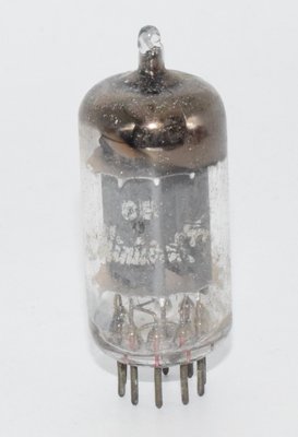
The E83CC is a double triode with separate cathodes, housed in a miniature all-glass envelope with a Noval (B9A) 9-pin base. Both triode systems are completely independent of each other. The heater filament has a center-tap brought out to the base, allowing the heaters of both systems to be connected either in parallel or in series for AC or DC operation.
Heater Data
| Parameter | Symbol | Parallel Operation | Series Operation | Unit |
|---|---|---|---|---|
| Heater Voltage | Uf | 6.3 | 12.6 | V |
| Heater Current | If | 0.3 | 0.15 | A |
| Warm-up Time | tf | 16 | s | |
The heater is indirectly heated with an oxide-coated cathode. When operating in series heater strings with other tubes, a current-limiting device must be used to limit inrush current at switch-on. System II (pin 4 and 5 side) should always be energized first, and pin 4 (heater center-tap) should be grounded.
Interelectrode Capacitances (Each System, System I and II)
| Parameter | Symbol | Value | Unit |
|---|---|---|---|
| Input Capacitance | Cg1 | 1.5 | pF |
| Output Capacitance | Ca | 0.45 | pF |
| Grid-to-Plate (Feedthrough) Capacitance | Ca/g1 | 1.7 | pF |
| Grid-to-Heater Capacitance | Cg1/f | <0.15 | pF |
Inter-System Capacitances
| Parameter | Symbol | Value | Unit |
|---|---|---|---|
| Grid I to Grid II | Cg1I/g1II | ≤0.01 | pF |
| Anode I to Anode II | CaI/aII | ≤0.2 | pF |
| Grid I to Anode II | Cg1I/aII | ≤0.03 | pF |
| Grid II to Anode I | Cg1II/aI | ≤0.03 | pF |
Note: The extremely low inter-system capacitances (grid I to grid II ≤0.01 pF) are critical for the E83CC's suitability in high-gain cascaded stages, where crosstalk between sections must be minimized.
Characteristic Values (Each System)
| Parameter | Symbol | Condition 1 | Condition 2 | Unit |
|---|---|---|---|---|
| Anode Voltage | Ua | 100 | 250 | V |
| Grid Bias Voltage | Ug1 | −1 | −2 | V |
| Anode Current | Ia | 0.5 | 1.2 | mA |
| Transconductance | S (gm) | 1.25 | 1.6 | mA/V |
| Amplification Factor | μ | 100 | 100 | — |
| Plate Resistance | Ri (rp) | 80 | 62.5 | kΩ |
Maximum Ratings (Each System)
| Parameter | Symbol | Maximum | Unit |
|---|---|---|---|
| Anode Voltage (cold, no signal) | Uao | 550 | V |
| Anode Voltage (operating) | Ua | 300 | V |
| Anode Dissipation | Wa | 1 | W |
| Cathode Current | Ik | 8 | mA |
| Grid Resistor (cathode bias) | Rg1 | 2.2 | MΩ |
| Grid Resistor (grid-leak bias) | Rg1 | 22 | MΩ |
| Negative Grid Voltage | −Ug1 | −50 | V |
| Cathode-to-Heater Voltage | Uk/f | 180 | V |
| External Cathode-to-Heater Resistance | Rk/f | 20 | kΩ |
| External Cathode-to-Heater Resistance (phase inverter) | Rk/f | 120 | kΩ |
| Grid Voltage for Grid Current Onset (Ig1 ≤ 0.3 μA) | Ug1i | −1.3 | V |
Pin Configuration (Noval B9A Base)
Viewed from the bottom of the socket (pin side):
| Pin | Connection |
|---|---|
| 1 | Anode I (aI) |
| 2 | Grid I (g1I) |
| 3 | Cathode I (kI) |
| 4 | Heater (center-tap) |
| 5 | Heater |
| 6 | Anode II (aII) |
| 7 | Grid II (g1II) |
| 8 | Cathode II (kII) |
| 9 | Heater |
Physical Dimensions
- Maximum diameter: 22.2 mm
- Overall height (seated): approximately 56.3 mm
- Bulb height: approximately 49.2 mm (from base seating plane)
- Maximum weight: 10 g
- Base: S 9/12 (Noval, per ČSN 35 8904)
Note: The E83CC typically features a more robust internal construction compared to the standard ECC83, with additional mica spacers, thicker support rods, and sometimes a frame-grid construction (particularly in Siemens and Telefunken production) to reduce microphonics. Exact physical dimensions may vary slightly between manufacturers but conform to the standard Noval miniature envelope.
3. Applications and Usage
The E83CC was designed as a low-frequency voltage amplifier and phase inverter — the same fundamental role as the ECC83 — but with specifications tightened for professional and critical applications. The Tesla datasheet explicitly states the ECC83 family is intended for use as a "low-frequency voltage amplifier and phase inverter" ("nízkofrekvenční zesilovač napětí a obraceč fáze").
Primary Applications
- RC-Coupled Voltage Amplifier: The datasheet provides extensive tables for RC-coupled amplifier design with cathode bias. With a supply voltage of 250V, anode load of 100 kΩ, and following grid resistor of 250 kΩ, a voltage gain of 52 is achievable. Higher gains up to 77 are possible with 300V supply, 500 kΩ anode load, and 1 MΩ following grid resistor, though at the expense of higher distortion.
- Phase Inverter (Cathodyne / Split-Load): The datasheet provides specific phase inverter operating data. At Ub = 250V with RaI = 100 kΩ, RaII = 100 kΩ, and Rk = 68 kΩ, a gain of 25 is achieved with only 1.8% distortion. At Ub = 350V with RaI = 150 kΩ, RaII = 150 kΩ, and Rk = 82 kΩ, a gain of 27 is achieved with 1.8% distortion.
- Cascaded Two-Stage Amplifier: Using both triode sections in cascade, gains of 58 to 62 are achievable with distortion figures between 1.1% and 5.5%, depending on operating conditions and supply voltage.
- Professional Audio Equipment: Studio mixing consoles, broadcast preamplifiers, and high-quality tape recorder electronics.
- Measurement and Instrumentation: Where low noise, low microphonics, and predictable characteristics are essential.
- High-Fidelity Preamplifiers: RIAA phono stages, line-level preamplifiers, and headphone amplifiers.
Design Tables — RC-Coupled Amplifier (Cathode Bias, One System)
The following table excerpts from the datasheet illustrate the range of voltage gains achievable with various component values (grid resistor Rg1 = 1 MΩ, coupling capacitors Cv = 10 kpF, cathode bypass capacitor Ck = 50 μF):
| Ub (V) | Ra (kΩ) | Rg1' (kΩ) | Rk (kΩ) | Voltage Gain (Uo/Ug1) |
|---|---|---|---|---|
| 100 | 100 | 100 | 1.7 | 33 |
| 100 | 100 | 250 | 2.0 | 40 |
| 100 | 250 | 250 | 3.5 | 44 |
| 100 | 500 | 1000 | 8 | 55 |
| 200 | 100 | 100 | 1.0 | 41 |
| 200 | 250 | 250 | 2.0 | 55 |
| 200 | 500 | 1000 | 5.0 | 64 |
| 250 | 100 | 100 | 0.9 | 44 |
| 250 | 250 | 250 | 1.8 | 57 |
| 250 | 500 | 1000 | 3 | 65 |
| 300 | 100 | 100 | 0.8 | 46 |
| 300 | 250 | 250 | 1.6 | 60 |
| 300 | 500 | 1000 | 3.5 | 70 |
Design Tables — RC-Coupled Amplifier with Cathode Bias (Detailed, One System)
With Rg1 = 1 MΩ, Cv (anode) = 0.1 μF, Cv (grid) = 10 kpF, Ck = 50 μF:
| Ub (V) | Ra (kΩ) | Rg1' (kΩ) | Rk (Ω) | Ia (mA) | Uo eff (V) | Gain | Distortion k (%) |
|---|---|---|---|---|---|---|---|
| 300 | 47 | 150 | 1000 | 1.55 | 26 | 40.0 | 5.0 |
| 300 | 100 | 330 | 1200 | 1.11 | 30 | 57 | 2.7 |
| 300 | 220 | 680 | 2200 | 0.63 | 36 | 72.0 | 2.6 |
| 400 | 47 | 150 | 680 | 2.45 | 37 | 44.0 | 3.6 |
| 400 | 100 | 330 | 820 | 1.72 | 38 | 63 | 1.7 |
| 400 | 220 | 680 | 1200 | 1.02 | 38 | 76.5 | 1.1 |
Note: Distortion is approximately proportional to output voltage.
4. Sound Characteristics
The E83CC has earned a distinguished reputation in the audio world, and its sonic character is frequently discussed among audiophiles, recording engineers, and guitar amplifier enthusiasts. While subjective descriptions of tube sound must always be taken in context — the surrounding circuit, passive components, power supply quality, and loudspeaker all contribute to the final result — there is a broad consensus on the E83CC's tonal qualities:
Tonal Signature
- Refined and Detailed: The E83CC is consistently described as more refined and detailed than standard ECC83/12AX7 tubes. The special-quality construction — tighter tolerances, better section matching, and reduced microphonics — translates into a cleaner, more transparent presentation with superior resolution of low-level detail.
- Smooth, Extended Highs: The treble response is typically characterized as smooth and extended without harshness or grain. This is partly attributable to the tube's low noise floor and well-controlled interelectrode capacitances (Ca/g1 = 1.7 pF), which help maintain bandwidth without introducing parasitic oscillation or HF distortion.
- Rich, Warm Midrange: Like all members of the ECC83 family, the E83CC exhibits the characteristic warm, harmonically rich midrange that has made this tube type a cornerstone of high-fidelity audio. The high amplification factor (μ = 100) combined with the relatively high plate resistance (62.5–80 kΩ) produces a characteristically "tubey" harmonic structure dominated by even-order harmonics, particularly second harmonic.
- Controlled, Articulate Bass: The bass response is typically described as tighter and more controlled than standard ECC83 types, with better definition and less bloat. This is likely a consequence of the tighter manufacturing tolerances and better internal damping.
- Low Microphonics: One of the most practically significant sonic advantages of the E83CC is its reduced susceptibility to microphonic noise — mechanical vibrations coupling into the audio signal. This is especially important in phono preamplifier stages where the tube operates at very high gain and any microphonic tendency is amplified enormously.
- Excellent Dynamics: The E83CC is noted for its dynamic range and ability to handle transients cleanly, maintaining composure during complex musical passages.
Manufacturer Variations
The sonic character of the E83CC varies somewhat depending on the manufacturer:
- Telefunken E83CC: Often considered the "holy grail" — prized for exceptional clarity, air, and three-dimensionality. Telefunken's frame-grid construction contributes to extremely low microphonics and noise.
- Siemens E83CC: Known for a slightly more analytical and precise presentation, with outstanding detail retrieval and a neutral tonal balance.
- Philips/Amperex E83CC: Tends toward a slightly warmer, more romantic presentation while retaining excellent detail. The Bugle Boy variants are particularly sought after.
- JJ Electronic E83CC: The current-production JJ E83CC offers a balanced, musical presentation that represents excellent value. It provides a warmer, slightly smoother character compared to some NOS types, with good noise performance for a modern tube.
Comparison with Standard ECC83/12AX7
Compared to a standard ECC83, the E83CC generally offers:
- Lower noise floor (typically 3–6 dB improvement)
- Reduced microphonics
- Better section-to-section matching (critical for phase inverter and differential amplifier applications)
- More consistent performance over the tube's lifetime
- A more refined, less "grainy" presentation
5. Equivalent and Substitute Types
The E83CC belongs to the large ECC83/12AX7 family. However, it is important to understand the distinction between electrically equivalent types and quality-grade equivalents. The E83CC is a special-quality version; while it is pin-compatible and electrically interchangeable with the standard ECC83, not all ECC83-family tubes meet the E83CC's tighter specifications.
Direct Equivalents (Same Electrical Characteristics, Standard Quality)
| Type | Notes |
|---|---|
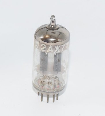
| ECC83 | Standard European designation; direct equivalent at standard quality level. The Tesla datasheet confirms it replaces foreign types 12AX7, B339, and CV492. |
| 12AX7 / 12AX7A | American RETMA designation; identical electrically. 12.6V/6.3V heater. |
| B339 | Philips designation; equivalent. |
| CV492 | British military designation for ECC83. |
| CV4004 | British military special-quality designation; closer in quality grade to E83CC. |
| M8137 | British military/Mullard special-quality designation; comparable quality grade to E83CC. |
| 7025 | American low-noise version of 12AX7; similar quality intent to E83CC. |
| ECC803 / ECC803S | Special-quality ECC83 variants; the 'S' denotes a further selection grade. Very close to E83CC in quality intent. |
Related Types (Different Ratings — NOT Direct Drop-In Replacements Without Consideration)
| Type | Notes |
|---|---|
| 5751 / 5751WA / CK5751 | Military-grade tube with μ ≈ 70 (vs. 100 for E83CC). Pin-compatible but lower gain — approximately 70% of E83CC gain. Often used as a lower-gain substitute in guitar amplifiers to reduce preamp distortion. |
| 6681 | Industrial version with different characteristics; verify specifications before substituting. |
| 12AX7WA | Ruggedized military version; electrically similar but may have slightly different characteristics. |
| 6057 | Special-quality 12AX7 variant. |
| CV8156 / CV8222 / CV8312 / CV10319 / CV4017 | Various British CV-registered versions with differing quality grades and specifications. |
| ECC863 | Variant designation; verify specifications against E83CC before substituting. |
| 7382 / 7494 / 7729 / 6L13 | Various industrial/military registered types in the 12AX7 family; specifications may differ in detail. |
| QB339 | Variant of B339. |
| E2164 | Related type; confirm specifications before use. |
Important Note: While all the above types share the Noval (B9A) base and the same pinout, and most are broadly interchangeable in terms of heater requirements and basic operating parameters, the E83CC's distinguishing feature is its quality grade — tighter tolerances on gain matching between sections, lower noise, lower microphonics, and longer guaranteed life. Substituting a standard 12AX7 for an E83CC will work electrically but may not meet the noise and matching specifications that the E83CC was selected for.
6. Notable Characteristics
High Amplification Factor
With μ = 100, the E83CC provides very high voltage gain per stage. This is both its greatest strength and a design consideration — the high gain means that any noise, hum, or microphonic disturbance at the grid is amplified 100 times at the plate. This is precisely why the E83CC's special-quality construction (reduced microphonics, lower noise) is so valuable.
High Plate Resistance
The plate resistance of 62.5 kΩ (at Ua = 250V, Ug1 = −2V) to 80 kΩ (at Ua = 100V, Ug1 = −1V) is relatively high for a small-signal triode. This means the tube works best with high-impedance loads (100 kΩ and above) and is not well-suited to driving low-impedance loads directly. The relationship μ = gm × rp holds: at 250V, 100 = 1.6 mA/V × 62.5 kΩ.
Low Operating Currents
The E83CC operates at very low anode currents — typically 0.5 mA to 1.2 mA under normal conditions, with a maximum cathode current of 8 mA per section. This contributes to long tube life and low heat generation, but also means the tube has limited current-delivery capability. The maximum anode dissipation is 1 W per section.
Exceptional Inter-System Isolation
The inter-system capacitances are remarkably low: grid I to grid II is ≤0.01 pF, and grid-to-opposite-anode capacitances are ≤0.03 pF. This excellent isolation between sections makes the E83CC ideal for cascaded gain stages within a single envelope, where coupling between stages could cause instability or degraded performance.
Wide Supply Voltage Range
The datasheet provides operating data for supply voltages from 100V to 400V, demonstrating the tube's versatility. At lower voltages (100–200V), the tube operates with reduced gain and headroom but remains functional — useful for portable or battery-powered equipment. At higher voltages (300–400V), maximum gain and output swing are achieved.
Grid Current Onset
Grid current begins to flow at approximately Ug1 = −1.3V (for Ig1 ≤ 0.3 μA). This sets the practical limit for signal swing at the grid — the input signal must not drive the grid more positive than about −1.3V to avoid grid current distortion. This is a relatively tight constraint and must be considered in circuit design, particularly in high-level stages.
Distortion Characteristics
The datasheet provides detailed distortion data for various operating conditions. Key observations:
- Distortion is approximately proportional to output voltage level.
- With Ra = 220 kΩ, Rg1' = 680 kΩ at Ub = 400V, distortion as low as 1.1% is achievable at 38V output.
- Lower anode loads (47 kΩ) produce higher distortion (3.6–8.5%) but at lower output impedance.
- The phase inverter configuration achieves very low distortion: 0.6% at Ub = 250V with appropriate component values.
Characteristic Curves
The datasheet includes comprehensive characteristic curves showing:
- Ia = f(Ug1) — Anode current vs. grid voltage at various anode voltages (50V to 300V)
- Ia = f(Ua) — Plate characteristics (anode current vs. anode voltage at various grid voltages from 0V to −4V)
- S, μ, D, Ri = f(Ia) — Transconductance, amplification factor, distortion, and plate resistance as functions of anode current at Ua = 100V, 200V, and 250V
- S = f(Ug1) — Transconductance vs. grid voltage at various anode voltages
- μ, Ri = f(Ug1) — Amplification factor and plate resistance vs. grid voltage at various anode voltages
- S, −Ug1 = f(Ua) — Transconductance and grid voltage vs. anode voltage at various anode currents
7. Usage in the Audio Community
The E83CC occupies a special place in the audio community, valued by both the high-fidelity and professional audio worlds. Its applications span from the most critical listening environments to professional recording studios.
High-Fidelity Preamplifiers
The E83CC is a top choice for high-end preamplifier designs, particularly in:
- Phono Preamplifiers (RIAA Stages): This is arguably the E83CC's most important application in modern hi-fi. The phono stage is the most demanding position for a small-signal tube — it must amplify the tiny signal from a phono cartridge (typically 0.5–5 mV for moving magnet) with extremely low noise and minimal microphonic interference. The E83CC's low noise floor and reduced microphonics make it ideal for this role. Many premium phono preamplifiers — from manufacturers such as Audio Research, Conrad-Johnson, Manley, and EAR — specify E83CC or equivalent special-quality tubes.
- Line-Stage Preamplifiers: While the demands are less extreme than in phono stages, the E83CC's superior noise performance and section matching benefit line-stage applications, particularly in balanced/differential topologies where matched sections are critical.
- Headphone Amplifiers: The growing popularity of tube headphone amplifiers has created new demand for E83CC tubes, where their low noise is appreciated in the intimate listening environment of headphones.
Guitar Amplifiers
While the standard 12AX7/ECC83 is the workhorse of guitar amplifier preamp stages, the E83CC is used by discerning players and boutique amplifier builders who seek:
- Lower noise floor for studio recording applications
- More consistent tone and response between amplifiers (due to tighter tolerances)
- Reduced microphonic feedback at high stage volumes
- A more refined, articulate clean tone
The E83CC is particularly valued in the first gain stage (V1) of guitar amplifiers, where its noise characteristics have the greatest impact on the overall signal-to-noise ratio.
Studio and Professional Audio
The E83CC was originally designed for professional applications, and it continues to serve in:
- Microphone Preamplifiers: High-end tube microphone preamps from manufacturers like Telefunken Elektroakustik, Manley, and Universal Audio use E83CC-grade tubes for their critical first gain stages.
- Studio Mixing Consoles: Vintage and modern tube-based mixing consoles benefit from the E83CC's consistency and low noise.
- Mastering Equipment: Where the absolute highest signal quality is required, E83CC tubes are specified in tube-based mastering equalizers and compressors.
The NOS Market
New-old-stock E83CC tubes from original European manufacturers have become highly collectible. Prices for genuine Telefunken, Siemens, or Amperex E83CC tubes can range from $100 to over $500 per tube, depending on manufacturer, production era, and testing results. Key identifiers for authentic NOS E83CC tubes include:
- Telefunken: Diamond-shaped bottom mark on the glass, frame-grid construction
- Siemens: Siemens logo, often with Halske designation on earlier production
- Amperex/Philips: Bugle Boy logo (Amperex), shield logo (Philips), with Heerlen or Hamburg factory codes
Current Production
JJ Electronic of Slovakia currently manufactures an E83CC, continuing the Central European tube-making tradition. The JJ E83CC is widely available and offers a cost-effective alternative to increasingly scarce and expensive NOS tubes. It is used in both new equipment designs and as a replacement tube in vintage gear. While it may not match the absolute performance of the finest NOS examples, it provides genuine E83CC-grade performance at a fraction of the NOS price and is a reliable, consistent choice for audio applications.
Typical Audio Circuit Recommendations
Based on the datasheet operating data, the following configurations are particularly well-suited for audio applications:
- Low-Distortion Voltage Amplifier: Ub = 300V, Ra = 220 kΩ, Rg1' = 680 kΩ, Rk = 2.2 kΩ — provides a gain of 72 with only 2.6% distortion at 36V output.
- Moderate-Gain, Low-Distortion Stage: Ub = 300V, Ra = 100 kΩ, Rg1' = 330 kΩ, Rk = 1.2 kΩ — provides a gain of 57 with 2.7% distortion at 30V output.
- Phase Inverter: Ub = 250V, RaI = 100 kΩ, RaII = 100 kΩ, Rk = 68 kΩ — provides a gain of 25 with only 1.8% distortion, with balanced outputs.
- High-Gain Cascaded Stage (Both Sections): Ub = 250V, RaI = 200 kΩ, RaII = 200 kΩ, Rk = 1 kΩ — provides a combined gain of 58 with 5.5% distortion at 35V output. For lower distortion (1.1%), the same configuration at Ub = 250V with Rk = 1 kΩ yields a gain of 58 at 7V output.
The E83CC remains one of the most respected and sought-after small-signal tubes in audio, bridging the gap between the ubiquitous ECC83/12AX7 and the demanding requirements of truly high-performance audio equipment. Whether in a vintage Marantz preamplifier, a modern boutique phono stage, or a professional studio microphone preamp, the E83CC continues to set the standard for what a high-quality double triode can achieve.