Introduction and History
The Philips E99F is a Special Quality (SQ) radio-frequency pentode with variable mutual conductance (variable-mu), designed specifically for mobile and transportable equipment where shock and vibration resistance are critical requirements. Manufactured by Philips under their prestigious SQ (Special Quality) designation, the E99F was introduced in the late 1950s, with tentative data first published on September 9, 1958, and revised specifications following on March 3, 1959.
The "E" prefix in the European Pro-Electron naming convention denotes a 6.3V heater voltage, while the "99" is a Philips-specific type number and "F" indicates a pentode construction. The SQ designation was Philips' mark of distinction for tubes manufactured to tighter tolerances and subjected to more rigorous quality control than their standard commercial equivalents. This made the E99F particularly suitable for professional, military, and high-reliability applications where consistent performance under adverse environmental conditions was paramount.
The E99F was designed during an era when mobile radio communications equipment — whether installed in vehicles, ships, or portable field units — demanded vacuum tubes that could withstand the rigors of transportation and operation in harsh environments. Its variable-mu characteristic made it ideal for use in AGC (Automatic Gain Control) circuits in RF and IF amplifier stages, where the gain of the tube could be smoothly controlled by varying the grid bias voltage.
Technical Specifications and Design
General Description
The E99F is a sharp-cutoff/variable-mu RF pentode with an indirectly heated cathode. It features a miniature (B7G / 7-pin miniature) base and a compact glass envelope. The tube is designed for both parallel and series heater supply configurations, making it versatile for various equipment designs.
Heater Ratings
| Parameter | Value |
|---|---|
| Heater Voltage (Vf) | 6.3 V |
| Heater Current (If) | 150 mA |
| Heating | Indirect, AC or DC; parallel or series supply |
| Heater Voltage Tolerance | ±20% allowed during short periods |
Interelectrode Capacitances (without external shield)
| Parameter | Typical (Column I) | Design Range (Column II) |
|---|---|---|
| Cag1 (Anode to Grid 1) | — | <0.0035 pF |
| Ca (Output capacitance) | 5.0 pF | 4.4–5.6 pF |
| Cg1 (Input capacitance) | 4.5 pF | 3.9–5.1 pF |
Typical Operating Conditions and Characteristics
| Parameter | Typical (Col. I) | Design Range (Col. II) | End of Life (Col. III) |
|---|---|---|---|
| Vf (Heater Voltage) | 6.3 V | — | — |
| If (Heater Current) | 150 mA | 142–158 mA | 142–158 mA |
| Vba (Anode Supply Voltage) | 250 V | — | — |
| Vbg2 (Screen Grid Supply Voltage) | 100 V | — | — |
| Vg3 (Suppressor Grid Voltage) | 0 V | — | — |
| Rk (Cathode Resistor) | 80 Ω | — | — |
| Ia (Anode Current) | 9.2 mA | 7.2–11.2 mA | 6.2 mA |
| Ig2 (Screen Grid Current) | 3.3 mA | 2.6–4.0 mA | — |
| S (Mutual Conductance / Transconductance) | 3.8 mA/V | 3.1–4.5 mA/V | 2.8 mA/V |
| μg2g1 (g2-g1 Amplification Factor) | 25 | — | — |
| Ri (Internal Resistance) | 1.0 MΩ | — | — |
| Req (Equivalent Noise Resistance) | 3.5 kΩ | — | — |
Characteristics at Reduced Bias (Vbg1 = -0.5 V)
| Parameter | Value |
|---|---|
| Vba | 250 V |
| Vbg2 | 100 V |
| Vg3 | 0 V |
| Vbg1 | -0.5 V |
| Rk | 80 Ω |
| Rg1 | 0.5 MΩ |
| -Ig1 (Grid 1 Current) | <0.2 μA (Col. II), 0.5 μA (Col. III) |
Cathode-to-Heater Ratings
| Parameter | Value (Col. II) | Value (Col. III) |
|---|---|---|
| Vkf (Cathode negative) | 100 V | — |
| R (Series Resistor) | 1 MΩ | — |
| Ikf | <15 μA | 15 μA |
Insulation Resistance
| Parameter | Value |
|---|---|
| Test Voltage | 300 V |
| Risol (between any two arbitrary electrodes) | >100 MΩ (Col. II), 50 MΩ (Col. III) |
Absolute Maximum Ratings (Limiting Values)
| Parameter | Maximum Value |
|---|---|
| Vao (Anode Voltage, no current) | 600 V |
| Va (Anode Voltage) | 330 V |
| Wa (Anode Dissipation) | 3.3 W |
| Vg2o (Screen Grid Voltage, no current) | 600 V |
| +Vg1 (Positive Grid 1 Voltage) | 0 V |
| -Vg1 (Negative Grid 1 Voltage) | 55 V |
| Ik (Cathode Current) | 17 mA |
| Vkf (Heater-Cathode Voltage) | 100 V |
| tbulb (Maximum Bulb Temperature) | 140 °C |
Note: The screen grid voltage (Vg2) and screen grid dissipation (Wg2) limits are defined by the derating curve shown on page A of the datasheet. The relationship between allowable Wg2 and Vg2 is non-linear; designers should consult the original graph.
Maximum Circuit Values
| Parameter | Maximum Value |
|---|---|
| Rg1 (Fixed Bias) | 0.5 MΩ |
| Rg1 (Automatic / Cathode Bias) | 1 MΩ |
Vibrational Noise Output
Tested under the following conditions: Vba = 250 V, Vbg2 = 100 V, Vg3 = 0 V, Ra = 2 kΩ, Rk = 80 Ω, Ck = 1000 μF, with vibrational acceleration of 2.5 g at a frequency of 25 c/s.
Noise output: max. 100 mVeff
Shock and Vibration Resistance
| Parameter | Value |
|---|---|
| Shock Resistance | About 500 g (NRL impact machine, 5 blows of hammer, lifted over 30° angle, in each of 4 different positions) |
| Vibration Resistance | 2.5 g for 32 hours at 25 c/s in each of 3 positions |
Life Expectancy
1000 hours under the following life-test conditions:
- Vf = 6.3 V
- Vba = 250 V
- Vg3 = 0 V
- Vbg2 = 100 V
- Rk = 80 Ω
- Rg1 = 500 kΩ
- Vkf (cathode negative) = 135 V
Note: The 135 V heater-to-cathode voltage is a test condition only and should not be interpreted as a suitable operating condition. Tube life and reliability are enhanced by operation at lower temperatures.
Pin Configuration (Miniature B7G Base)
Viewed from the bottom of the tube (pin side):
| Pin | Connection |
|---|---|
| 1 | g1 (Control Grid) |
| 2 | k (Cathode) |
| 3 | f (Heater/Filament) |
| 4 | f (Heater/Filament) |
| 5 | a (Anode/Plate) |
| 6 | g2 (Screen Grid) |
| 7 | g3, s (Suppressor Grid, connected to shield) |
Physical Dimensions
- Maximum diameter: 19 mm
- Maximum seated height: 47.6 mm
- Maximum overall height: 54 mm
- Base: Miniature (B7G, 7-pin)
Design Recommendations
Philips explicitly recommends circuit operation with cathode bias (automatic bias via cathode resistor) rather than fixed bias for improved reliability and stability.
Applications and Usage
The E99F was designed primarily for the following applications:
- RF Amplifier Stages: The tube's variable-mu characteristic and low anode-to-grid capacitance (Cag1 < 0.0035 pF) make it exceptionally well-suited for RF amplifier stages in radio receivers and communications equipment. The extremely low feedback capacitance allows stable high-frequency amplification without neutralization in many circuit configurations.
- IF Amplifier Stages: With its controlled variable-mu characteristic, the E99F excels in intermediate frequency amplifier stages where AGC (Automatic Gain Control) is employed. The smooth gain control range, from full transconductance down to very low values as the grid bias is increased negatively, allows for effective signal level management.
- Mobile and Transportable Equipment: The primary design intent of the E99F was for use in mobile radio equipment — vehicle-mounted communications systems, portable field radios, shipboard electronics, and similar applications where mechanical shock and vibration are unavoidable. The tube's exceptional shock resistance (500 g) and vibration resistance (2.5 g at 25 Hz for 32 hours) far exceed those of standard commercial tubes.
- Military and Professional Communications: The SQ designation and rugged construction made the E99F a natural choice for military radio equipment and professional communications systems where reliability under adverse conditions was essential.
- Mixer/Converter Stages: The pentode can also serve in frequency converter circuits, though this was a secondary application.
The tube's tolerance for heater voltage variations of ±20% during short periods was a significant advantage in mobile applications where power supply regulation might be compromised by engine starting, generator fluctuations, or battery voltage variations.
Sound Characteristics
While the E99F was designed as an RF/IF pentode rather than an audio tube, its electrical characteristics give it a distinctive sonic signature when pressed into audio service — a practice that has gained some following among adventurous tube audio enthusiasts:
- Clean and Detailed: The E99F's relatively high transconductance of 3.8 mA/V combined with its very high internal resistance of 1.0 MΩ produces a high voltage gain capability. When used as a voltage amplifier in audio circuits, this translates to a clean, detailed, and articulate sound with excellent resolution of fine musical details.
- Low Microphonics: Thanks to its shock and vibration-resistant construction, the E99F exhibits exceptionally low microphonic noise — a characteristic highly prized in audio applications, particularly in high-gain preamplifier stages where microphonics can be a serious problem. The maximum vibrational noise output of 100 mVeff under severe test conditions is remarkably low.
- Extended and Airy Highs: The tube's RF heritage means its internal construction is optimized for high-frequency performance. In audio applications, this manifests as an extended, airy high-frequency response with excellent transient detail and a sense of openness in the upper registers.
- Tight, Controlled Bass: The high plate resistance and pentode characteristics tend to produce a tighter, more controlled bass response compared to triode-connected alternatives. Some listeners describe the low end as precise and well-defined rather than warm and full.
- Neutral Tonal Balance: As a Special Quality tube built to tight tolerances, the E99F tends toward a neutral, uncolored tonal balance. It does not impose a strong "character" on the signal in the way that some more famous audio tubes do, making it appealing to those who prefer accuracy over euphonic coloration.
- Low Noise Floor: The SQ manufacturing standards and the tube's inherently low equivalent noise resistance (Req = 3.5 kΩ) contribute to a very low noise floor, allowing quiet backgrounds and excellent dynamic range in audio circuits.
It should be noted that the E99F's sonic character is best appreciated in voltage amplifier and preamplifier roles. Its relatively modest anode dissipation of 3.3 W limits its usefulness as an output tube, though it can serve effectively in low-power single-ended output stages or as a driver tube.
Equivalent or Substitute Types
The E99F is a relatively specialized Philips type, and direct equivalents are limited:
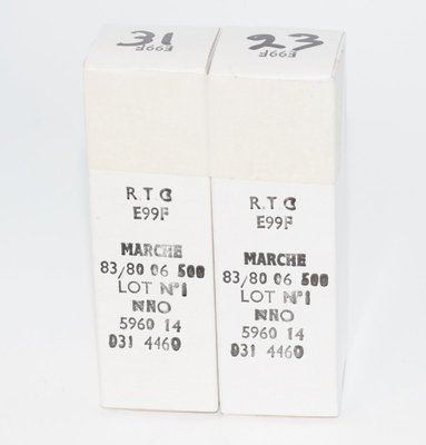
- RTC E99F: RTC (Radiotechnique-Compelec), the French subsidiary of Philips, manufactured the E99F to identical specifications. RTC-branded E99F tubes are fully interchangeable and are sometimes found as NOS (New Old Stock) pairs. These are genuine equivalents with identical pinout, ratings, and characteristics.
- Mullard E99F: As another Philips subsidiary, Mullard may have produced or distributed the E99F under their own branding. These would be electrically identical.
- Amperex E99F: The Amperex division of Philips in the United States may have handled distribution of this type. Again, electrically identical.
There is no widely recognized direct American (RETMA/EIA) equivalent for the E99F. While it shares some general characteristics with other variable-mu RF pentodes such as the EF85 or EF89 family, these are not direct substitutes — they differ in pinout, operating conditions, and/or electrical characteristics. The 6BA6/EF93 is another variable-mu miniature pentode that is sometimes mentioned in the same context, but it has different ratings and is not a drop-in replacement.
Caution: Do not substitute other pentode types without carefully verifying pinout compatibility, heater requirements, and operating point suitability. The E99F's specific characteristics — particularly its shock resistance and variable-mu behavior — are not easily replicated by other types.
Notable Characteristics
- Exceptional Ruggedness: The E99F's shock resistance of approximately 500 g and vibration resistance of 2.5 g at 25 Hz for 32 hours are outstanding specifications that set it apart from standard commercial tubes. These ratings were verified using the NRL (Naval Research Laboratory) impact machine test protocol, a rigorous military-standard test procedure involving 5 blows of a hammer lifted over a 30° angle in each of four different tube positions.
- Ultra-Low Feedback Capacitance: The anode-to-grid-1 capacitance of less than 0.0035 pF is remarkably low, enabling stable high-frequency amplification and minimizing unwanted feedback paths. This is a key parameter for RF amplifier design.
- Variable-Mu Characteristic: The E99F features a variable mutual conductance (remote cutoff) characteristic, allowing smooth gain control over a wide range. The transconductance varies from approximately 3.8 mA/V at the normal operating point down to very low values as the grid bias is increased to -20 V or beyond, with a cutoff bias range extending to -55 V maximum.
- Heater Voltage Tolerance: The ±20% heater voltage tolerance during short periods is a significant practical advantage for mobile applications where supply voltages may fluctuate.
- SQ Manufacturing Standards: The Special Quality designation ensured tighter parameter spreads, more rigorous incoming inspection, and better long-term reliability compared to standard commercial tubes. The datasheet provides three columns of data: Column I (typical values for new tubes), Column II (design range for equipment design), and Column III (end-of-life values), giving designers comprehensive information for reliable circuit design.
- High Insulation Resistance: The requirement for insulation resistance greater than 100 MΩ at 300 V between any two arbitrary electrodes (50 MΩ at end of life) indicates the high-quality construction and materials used in the E99F.
- Cathode Bias Recommended: Philips explicitly recommends operation with cathode bias (automatic bias) rather than fixed bias, which improves stability and extends tube life by providing a degree of self-regulation.
- Low Equivalent Noise Resistance: At Req = 3.5 kΩ, the E99F offers good noise performance for an RF pentode, making it suitable for front-end amplifier stages where signal-to-noise ratio is critical.
Usage in the Audio Community
The Philips E99F occupies a niche but respected position in the tube audio community. While it was never designed as an audio tube, several factors have drawn the attention of audiophiles and DIY tube amplifier builders:
Preamplifier and Phono Stage Applications
The E99F's combination of high gain capability, low microphonics, and low noise make it an attractive candidate for high-gain preamplifier stages, particularly in phono preamplifiers where microphonic sensitivity and noise floor are critical parameters. The tube's SQ construction ensures that microphonic artifacts — a common complaint with many miniature pentodes — are minimized to levels that are essentially inaudible in normal listening environments.
Pentode Voltage Amplifier Stages
Some audio designers have incorporated the E99F as a pentode voltage amplifier in line-stage preamplifiers and as a driver stage for power amplifiers. The high voltage gain available from a single pentode stage (the product of transconductance and load resistance can yield gains of several hundred) allows simpler circuit topologies with fewer gain stages, which some designers believe results in a more transparent and immediate sound.
Triode-Connected Operation
A popular approach in the audio community is to connect the E99F in triode mode by tying the screen grid (g2) to the anode. This sacrifices some gain but significantly reduces the plate resistance and produces a more linear transfer characteristic. In triode mode, the E99F behaves as a medium-mu triode with characteristics that some listeners find more musically engaging than the pentode configuration, offering a warmer tonal balance with more even-order harmonic content.
Collector Appeal and Rarity
The E99F is not a common tube, and NOS examples — particularly those with the Philips SQ marking or the RTC France branding — are sought after by collectors and audio enthusiasts. The tube's relative obscurity means that prices have historically been more reasonable than for more famous audio types, though this is changing as awareness grows. Matched pairs of RTC E99F NOS tubes are occasionally available from specialist vintage tube dealers.
DIY Community Projects
The DIY tube audio community has explored the E99F in various experimental circuits, including:
- Single-ended pentode headphone amplifiers, where the 3.3 W maximum anode dissipation is sufficient for driving high-impedance headphones
- RIAA phono preamplifiers exploiting the tube's low noise and low microphonics
- Line-stage preamplifiers using the pentode's high gain to achieve the required voltage amplification in a single stage
- Buffer stages in DAC output circuits, where the tube's neutrality and low coloration are valued
Practical Considerations for Audio Use
Audio designers working with the E99F should note several practical considerations:
- The recommended cathode bias operation (80 Ω cathode resistor for the standard operating point) simplifies circuit design and improves long-term stability.
- The maximum grid resistor values (0.5 MΩ for fixed bias, 1 MΩ for automatic bias) must be respected to prevent grid current issues and ensure reliable operation.
- The tube's variable-mu characteristic means that the transfer curve is not perfectly exponential — at very low bias levels, the transconductance is high and relatively linear, which is the region most useful for audio applications.
- The suppressor grid (pin 7) is internally connected to the shield and should be connected to cathode potential in most audio circuits.
- The maximum bulb temperature of 140°C should be considered in enclosed chassis designs; adequate ventilation is important for long tube life.
While the E99F will never rival the ECC83/12AX7 or EF86 in terms of widespread audio adoption, it represents an interesting and high-quality alternative for the discerning tube audio designer who values low noise, low microphonics, and the distinctive sonic character of a well-made Philips SQ pentode.