Introduction and History
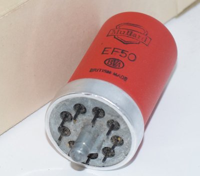
The Mullard EF50 is one of the most historically significant vacuum tubes ever manufactured. Classified as a single-ended short wave high-frequency pentode, the EF50 played a pivotal role in the Allied victory during World War II, serving as the critical active element in British airborne radar systems. Its development in the late 1930s by Philips/Mullard represented a quantum leap in valve design, introducing construction techniques that would influence tube manufacturing for decades to come.
The EF50 was originally developed at the Philips research laboratories in Eindhoven, Netherlands, around 1938. When the German invasion of the Netherlands became imminent in May 1940, the tooling, production machinery, and technical expertise for the EF50 were evacuated to the Mullard factory at Blackburn, Lancashire, England, in what became one of the most dramatic industrial rescues of the war. This transfer ensured that production of this vital component could continue uninterrupted for the British war effort.
The tube was designed specifically for high-frequency applications, particularly radar receivers operating in the VHF and early UHF ranges. Its all-glass B9G (Loctal-style) base with a single-ended pin configuration was revolutionary for its time, offering dramatically reduced lead inductance and inter-electrode capacitances compared to the octal-based tubes then in common use. The EF50 became the backbone of British radar receivers, including those used in the critical AI (Airborne Interception) radar sets that helped the RAF achieve air superiority during the Battle of Britain and the night Blitz.
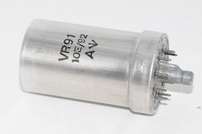
Production numbers were staggering — tens of millions of EF50s were manufactured during the war years. The tube was produced by Mullard, and also under various military designations including VR91, VR91A, CV1091, CV1578, ARP35, and the American designation VT250. Post-war, the EF50 continued to find wide application in television receivers, laboratory instruments, and communications equipment throughout the late 1940s and 1950s.
Technical Specifications and Design
Heater
| Heater Voltage (Vf) | 6.3 V |
| Heater Current (If) | 0.300 A |
Inter-Electrode Capacitances
| Parameter | Condition | Value |
|---|---|---|
| Cagl (Anode to Grid 1) | Valve cold | < 0.003 pF |
| Cg1 (Grid 1 input) | Valve cold | 7.8 pF |
| Ca (Anode output) | Valve cold | 5.3 pF |
| Cg1f (Grid 1 to heater) | Valve cold | < 0.01 pF |
| Cg1 (Grid 1 input) | Valve warm (Ia = 10 mA) | 10 pF |
| Ca (Anode output) | Valve warm (Ia = 10 mA) | 5.3 pF |
The extremely low anode-to-grid 1 capacitance (Cagl < 0.003 pF) was a key design achievement, enabling stable high-frequency amplification without neutralisation — a remarkable feat for the era.
Damping (at 6 m wavelength, Ia = 10 mA)
| Rg1 (Grid 1 damping resistance) | 4,000 ohms |
| Ra (Anode damping resistance) | 50,000 ohms |
Capacitance Limits
| Parameter | Condition | Max | Min |
|---|---|---|---|
| Cg1 | Cold | 8.2 pF | 7.4 pF |
| Ca | Cold | 5.7 pF | 4.9 pF |
| Cg1 | Warm | 10.6 pF | 9.4 pF |
| Ca | Warm | 5.9 pF | 4.7 pF |
Operating Conditions — Controlled by Grid 3
| Parameter | Condition 1 (Vg3 = 0) | Condition 2 (Vg3 = -54 V) |
|---|---|---|
| Va | 250 V | 250 V |
| Vg2 | 250 V | 250 V |
| -Vg1 | 2 V | 2 V |
| -Vg3 | 0 V * | 54 V ** |
| Ia | 10 mA | — |
| Ig2 | 3 mA | — |
| Sg1/a (Transconductance) | 6.5 mA/V | 0.45 mA/V |
| Ri (Internal resistance) | 1 MΩ | — |
| g (g1/g2) | 75 | — |
| Raeq. | 1,400 ohms | — |
* Valve not controlled by A.V.C.
** For a 15:1 drop in mutual conductance (S g1/a).
Operating Conditions — Controlled by Grid 1 (with Rk = 32 ohms, Ck = 50 µF)
| Parameter | Condition 1 (Vg3 = 0) | Condition 2 (Vg3 = -4.5 V) |
|---|---|---|
| Va | 250 V | 250 V |
| Vg2 | 250 V | 250 V |
| Vg3 | 0 V | 0 V |
| -Vg1 | 1.55 V * | 4.5 V *** |
| Ia | 10 mA | — |
| Ig2 | 3 mA | — |
| Sg1/a (Transconductance) | 6.5 mA/V | 0.65 mA/V |
| Ri (Internal resistance) | 1 MΩ | — |
* Valve not controlled by A.V.C.
*** For a 10:1 drop in mutual conductance (S g1/a).
Operating Conditions — Controlled by Grids 1 and 3 via Potentiometer
Potentiometer of 50,000 + 3,000 ohms
| Parameter | Condition 1 | Condition 2 |
|---|---|---|
| Va | 250 V | 250 V |
| Vg2 | 250 V | 250 V |
| -Vg1 & 3 | 30 V * | 55.5 V *** |
| Ia | 10 mA | — |
| Ig2 | 5.5 mA | — |
| Sg1/a | 5.2 mA/V | 0.52 mA/V |
| Ri | 0.1 MΩ | — |
Potentiometer of 50,000 + 4,000 ohms (with Rk = 32 ohms, Ck = 50 µF)
| Parameter | Condition 1 | Condition 2 |
|---|---|---|
| Va | 250 V | 250 V |
| Vg2 | 250 V | 250 V |
| -Vg1 & 3 | 20 V * | 51.5 V *** |
| Ia | 10 mA | — |
| Ig2 | 4 mA | — |
| Sg1/a | 6 mA/V | 0.6 mA/V |
| Ri | 0.2 MΩ | — |
Maximum Ratings (Limits)
| Vao max (Anode supply voltage) | 550 V |
| Va max (Anode voltage) | 300 V |
| Wa max (Anode dissipation) | 3 W |
| Ik max (Cathode current) | 15 mA |
| Vg2o max (Screen supply voltage) | 550 V |
| Vg2 max (Screen voltage) | 300 V |
| Wg2 max (Screen dissipation) | 1.7 W |
| -Vg1 max (at Ig1 = +0.3 µA) | 1.3 V |
| -Vg3 max (at Ig3 = +0.3 µA) | 1.3 V |
| Rg1 max (Grid 1 resistance) | 3 MΩ |
| Rg3 max (Grid 3 resistance) | 3 MΩ |
| Vfk max (Heater-cathode voltage) | 100 V |
| Rfk max (Heater-cathode resistance) | 20,000 ohms |
Key Derived Parameters (at Va = 250 V, Vg2 = 250 V, Vg3 = 0 V, -Vg1 = 2 V)
| Transconductance (gm / Sg1/a) | 6.5 mA/V |
| Anode Resistance (Ri) | 1 MΩ |
| Amplification Factor (µ) | ~6,500 (derived from gm × Ri) |
| g (g1/g2) ratio | 75 |
| Equivalent Noise Resistance (Raeq.) | 1,400 ohms |
Physical Construction
- Base Type: B9G (British 9-pin single-ended all-glass base, also known as the Philips/Mullard loctal-style base)
- Envelope: Glass with metal screening can (34 mm max diameter, 62 mm max height including base)
- Mounting: Vertical, base down preferred
- Pin Configuration (viewed from below): The B9G base features 9 pins arranged in a circle with a central spigot for alignment. Pins are assigned as: h, h (heater), s (screen/internal shield), g1 (grid 1/control grid), a (anode), g3 (suppressor grid/grid 3), k (cathode), g2 (screen grid/grid 2), s (screen/internal shield).
Applications and Usage
Military Applications
The EF50 was designed first and foremost as a high-frequency amplifier for radar receivers. Its primary wartime applications included:
- Airborne Interception (AI) Radar: The EF50 was the key tube in the AI Mk. IV and subsequent radar sets that equipped RAF night fighters. These systems were instrumental in countering the German night bombing campaign.
- Ground-based radar: Chain Home Low (CHL) and other ground radar installations used the EF50 extensively in their receiver chains.
- Naval radar: Royal Navy radar sets employed the EF50 in IF amplifier strips.
- IFF (Identification Friend or Foe): Early IFF transponder and interrogator systems used the EF50.
- Electronic countermeasures: Various ECM receivers and direction-finding equipment relied on the EF50's high-frequency performance.
The tube's variable-mu capability (controlled via grid 3, grid 1, or both grids simultaneously via a potentiometer network) made it particularly suitable for AGC (Automatic Gain Control) applications in radar IF strips, where the ability to handle a wide dynamic range of signal levels was essential.
Post-War Commercial Applications
After the war, vast quantities of surplus EF50s became available, and the tube found widespread use in:
- Television receivers: The EF50 was widely used in early British television sets as an IF amplifier, video amplifier, and in various other stages.
- Communications receivers: High-quality shortwave and VHF receivers used the EF50 as an RF amplifier, mixer, and IF amplifier.
- Laboratory instruments: Oscilloscopes, signal generators, and other test equipment employed the EF50 for its excellent high-frequency characteristics.
- Wide-band amplifiers: The tube's combination of high transconductance and low capacitances made it suitable for video and pulse amplifier applications.
- Audio preamplifiers: Though not its primary design intent, the EF50 found use in microphone preamplifiers and other audio front-end stages.
AGC/AVC Operating Modes
The Mullard datasheet specifies several distinct AGC control configurations:
- Grid 3 control only: The suppressor grid (g3) is used as the gain control element, with g1 fixed at -2 V bias. This provides a 15:1 mutual conductance reduction range (from 6.5 mA/V down to 0.45 mA/V) with a control voltage swing from 0 V to -54 V on g3.
- Grid 1 control only: The control grid (g1) is used for gain control with g3 at 0 V and cathode bias via Rk = 32 ohms with Ck = 50 µF. This provides a 10:1 mutual conductance reduction range (from 6.5 mA/V to 0.65 mA/V) with a control voltage swing from -1.55 V to -4.5 V on g1.
- Combined g1 and g3 control via potentiometer: Both grids are controlled simultaneously through a potentiometer network (50,000 + 3,000 ohms or 50,000 + 4,000 ohms), providing the widest AGC range with smooth gain reduction characteristics.
Sound Characteristics
Although the EF50 was designed as an RF/IF pentode rather than an audio tube, it has developed a devoted following among audio enthusiasts who appreciate its distinctive sonic qualities when pressed into audio service. The sound characteristics of the EF50 are shaped by its high transconductance (6.5 mA/V), very high plate resistance (1 MΩ), and its wartime-era construction quality.
Tonal Qualities
- Detail and clarity: The EF50's high gm and low noise (Raeq. of 1,400 ohms) translate into excellent signal resolution. In phono stages and microphone preamplifiers, the tube reveals fine detail and micro-dynamics with a clarity that many listeners find captivating.
- Midrange character: The EF50 is often described as having a rich, slightly warm midrange with excellent presence. Vocals and acoustic instruments are rendered with a natural, organic quality that audiophiles associate with the best British valves of the era.
- High-frequency extension: Given its RF heritage, the EF50 exhibits excellent high-frequency response with a smooth, airy top end that avoids the harshness sometimes associated with later miniature pentodes. The treble is typically described as extended but refined.
- Low-frequency performance: The bass response is generally considered clean and well-defined, though not as weighty or authoritative as some dedicated audio pentodes. The high plate resistance means that careful attention to load impedance and decoupling is required to achieve optimal low-frequency performance.
- Noise floor: Well-selected EF50s can be remarkably quiet for their age, with the equivalent noise resistance of 1,400 ohms being competitive with many later designs. However, due to the age of surviving specimens and the wide variation in wartime production quality, individual tubes can vary significantly in noise performance.
- Harmonic signature: When operated within its linear region, the EF50 produces a predominantly second-harmonic distortion signature that is musically pleasant. As a pentode, it also generates some higher-order harmonics, but these tend to be at lower levels than in many comparable types.
Manufacturer Variations
Audiophiles have noted significant sonic differences between different production batches and manufacturers:
- Mullard Red (metal can): The most sought-after variant, the Mullard Red EF50 is prized for its warm, musical presentation with excellent dynamics and a particularly sweet midrange. These early production tubes are considered the gold standard.
- Mullard standard production: Later Mullard production tubes are generally considered very good, with a slightly more neutral tonal balance than the Red variants.
- Sylvania/American production (VT250): American-made equivalents tend to have a slightly different character, often described as more analytical with a leaner tonal balance.
- Post-war European production: Various European manufacturers produced EF50s in the post-war period, with quality and sonic characteristics varying considerably.
Equivalent or Substitute Types
The following types are direct equivalents or close substitutes for the Mullard EF50, sharing the same B9G base, pinout, and electrical characteristics:
| Designation | Type | Notes |
|---|---|---|
| VR91 | British military designation | Direct equivalent. The most common wartime designation. Fully interchangeable. |
| VR91A | British military designation | Direct equivalent. Selected/improved version of VR91. Fully interchangeable. |
| CV1091 | British CV (Common Valve) designation | Direct equivalent. Post-war standardised designation. Fully interchangeable. |
| CV1578 | British CV designation | Direct equivalent. Alternative CV registration. Fully interchangeable. |
| ARP35 | British military designation | Direct equivalent. Air Ministry/RAF designation. Fully interchangeable. |
| VT250 | American military designation | Direct equivalent. US Signal Corps designation for American-produced EF50s. Fully interchangeable. |
Important note: All of the above designations refer to the same fundamental valve type and are fully interchangeable without any circuit modifications. They share identical pinouts, heater requirements, and electrical characteristics, differing only in their designation system and sometimes in the specific manufacturer or production standard applied.
The EF50 should not be confused with the later EF80 (B9A/Noval base) or EF86 (B9A/Noval base), which are entirely different tubes with different bases and pinouts, despite being pentodes designed for somewhat overlapping applications. The EF50 uses the older B9G base and cannot be substituted with any Noval-based tube without a complete socket change and circuit redesign.
Notable Characteristics
The Tube That Won the War
The EF50 has been described by historians as one of the most important electronic components of World War II. Without it, British radar would have been severely compromised. The dramatic evacuation of the production tooling from the Netherlands to England in 1940, just ahead of the German invasion, is one of the great stories of wartime industrial espionage and logistics. Had the Germans captured the Philips factory and its EF50 production capability, the course of the air war over Britain might have been very different.
Revolutionary Construction
The EF50 introduced several construction innovations that were ahead of their time:
- All-glass base: The B9G base eliminated the traditional Bakelite base, reducing losses at high frequencies and improving reliability.
- Single-ended construction: All connections emerge from one end of the tube, minimising lead lengths and reducing stray capacitances — critical for VHF performance.
- Internal screening: The tube incorporates internal electrostatic screening between the input and output sections, contributing to the extraordinarily low anode-to-grid capacitance of less than 0.003 pF.
- Metal screening can: The external metal can provides additional RF shielding and mechanical protection.
- Compact dimensions: At only 34 mm diameter and 62 mm height (maximum), the EF50 was remarkably compact for its era, enabling dense packaging in radar equipment.
Variable-Mu Capability
The EF50's ability to operate as a variable-mu (remote cutoff) pentode through multiple control methods — grid 3 alone, grid 1 alone, or both grids simultaneously — gave circuit designers exceptional flexibility in implementing AGC systems. The datasheet documents AGC ranges of 15:1 (via g3) and 10:1 (via g1) in mutual conductance, with even wider ranges achievable through combined control.
High Transconductance
The mutual conductance of 6.5 mA/V at the standard operating point (Va = 250 V, Vg2 = 250 V, Ia = 10 mA) was exceptionally high for a tube of this era and size, enabling high gain per stage in IF amplifier strips. Combined with the 1 MΩ plate resistance, this yields an amplification factor (µ) of approximately 6,500.
Reliability Concerns
Despite its excellent electrical design, the EF50 was not without problems. Wartime production pressures led to variable quality control, and the tube was known to suffer from:
- Microphony — the internal electrode structure could be sensitive to vibration, a significant issue in airborne applications.
- Intermittent connections at the B9G base pins, particularly in harsh environments.
- Variation in characteristics between production batches and manufacturers.
These issues led to the development of improved versions and eventually to the tube's replacement by more robust miniature types such as the EF80 in the post-war period.
Usage in the Audio Community
Despite being designed as an RF/IF pentode, the EF50 has carved out a niche in the audio community, particularly among enthusiasts who value vintage character and historical significance in their equipment.
Phono Preamplifiers
The EF50's high transconductance (6.5 mA/V) and relatively low equivalent noise resistance (1,400 ohms) make it a viable candidate for phono preamplifier input stages. Several boutique amplifier builders have designed phono stages around the EF50, taking advantage of its high gain to amplify the tiny signals from moving-magnet and even moving-coil cartridges. The tube's RF heritage means it handles fast transients well, which translates to excellent tracking of the complex waveforms found in vinyl playback.
Microphone Preamplifiers
The EF50 has found application in microphone preamplifier designs, where its combination of high gain, reasonable noise performance, and distinctive tonal character can be exploited. Some recording engineers and studio equipment builders have created EF50-based mic preamps that impart a vintage British character to recordings, particularly valued for vocals and acoustic instruments.
Line-Stage Preamplifiers
In line-stage applications, the EF50 can provide substantial voltage gain in a single stage. Its high plate resistance (1 MΩ) requires careful attention to load impedance matching, but when properly implemented, the tube can deliver excellent linearity and dynamic range. Some designers operate the EF50 in triode-strapped mode (with the screen grid tied to the anode) to reduce the plate resistance and achieve a more triode-like sound character, though this sacrifices much of the tube's gain advantage.
Headphone Amplifiers
A small but enthusiastic community of DIY audio builders has experimented with EF50-based headphone amplifiers. The tube's high gain makes it suitable for driving headphones when used with an appropriate output stage, and its compact size allows for relatively small amplifier builds.
Collectibility and Availability
The EF50 occupies an interesting position in the tube collecting world. Due to the enormous wartime production quantities, the tube is still relatively available compared to many other vintage types, though prices have risen significantly as audio demand has increased. The most sought-after variants include:
- Mullard Red (metal can) NOS: The premium variant, commanding the highest prices. These early-production Mullard tubes are prized for their superior construction quality and musical sound.
- Early Mullard production: Pre-1945 Mullard tubes with original wartime markings are highly collectible.
- Military-marked specimens: Tubes bearing VR91, ARP35, or CV1091 markings are popular with both collectors and audio users.
When selecting EF50s for audio use, it is important to test for microphony (tap the tube gently while monitoring the output), noise (hiss and hum), and emission (transconductance should be close to the 6.5 mA/V specification). Due to the age of these tubes — most are now 75-80+ years old — careful selection and testing is essential.
Circuit Design Considerations for Audio Use
Designers working with the EF50 in audio circuits should note several important considerations:
- The B9G socket is less common than octal or noval types and may require sourcing from specialist suppliers.
- The maximum anode dissipation of 3 W and maximum screen dissipation of 1.7 W must be respected to ensure tube longevity.
- The maximum cathode current of 15 mA limits the operating point options.
- The heater-cathode voltage maximum of 100 V allows reasonable flexibility in circuit topology.
- The maximum grid 1 resistance of 3 MΩ is generous and allows high-impedance input circuits.
- Adequate RF decoupling and screening should be employed, as the tube's excellent HF response means it can easily oscillate if layout is poor.
- The internal screening and low Cagl (< 0.003 pF) that made the tube excellent for RF work also contribute to stability in high-gain audio circuits.
The EF50 remains a fascinating tube that bridges the worlds of military history, vintage electronics, and modern audio enthusiasm. Its combination of historical significance, excellent technical performance, and distinctive sonic character ensures its continued relevance in the audio community for years to come.