Introduction and History
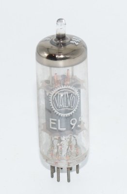
The EL95 is a miniature output pentode manufactured by Philips, originally designed for use in car radio receivers (Autoempfänger). First documented in the Philips Electronic Tube Handbook with data sheets dating from 1956–1957, the EL95 was engineered to operate efficiently from 12-volt automotive electrical systems, where heater power had to be carefully managed and space was at a premium.
During the mid-1950s, the European automotive radio market was expanding rapidly, and manufacturers needed compact, efficient output tubes that could deliver reasonable audio power while operating from the limited voltage supplies available in vehicles. The EL95 answered this need with its miniature B7G envelope, modest heater current draw, and the ability to operate from vibrator-type power supplies commonly used in car radios of the era. The tube was produced by Philips and its associated brands, including Valvo in Germany, Mullard in the UK, and Amperex in the United States.
The EL95 occupies an interesting niche in the vacuum tube world — it is neither a high-power output tube nor a simple small-signal device. With a maximum anode dissipation of 6 watts and the ability to deliver up to 3 watts of audio output in single-ended Class A operation, it sits in the category of compact power pentodes that were the workhorses of portable and mobile audio equipment in the 1950s and 1960s.
Technical Specifications and Design
General Description
The EL95 is an indirectly heated output pentode in a miniature glass envelope, using a 7-pin miniature (B7G) base. It was specifically designed for audio output stages in car radio receivers, with provisions for heater operation in parallel supply or with two tubes in series from a 12V battery.
Heater Data
| Parameter | Value |
|---|---|
| Heater Voltage (Vf) | 6.3 V |
| Heater Current (If) | 200 mA |
| Heater Type | Indirect, AC supply |
The heater is designed for parallel supply from AC, or two tubes may be connected in series and fed from a 12V battery — a key feature for automotive applications.
Typical Characteristics (at Va = Vg2 = 250V)
| Parameter | Symbol | Value |
|---|---|---|
| Anode Voltage | Va | 250 V |
| Screen Grid Voltage | Vg2 | 250 V |
| Control Grid Voltage | Vg1 | -9.0 V |
| Anode Current | Ia | 24 mA |
| Screen Grid Current | Ig2 | 4.5 mA |
| Transconductance | S (gm) | 5.0 mA/V |
| Plate Resistance | Ri | 80 kΩ |
| Amplification Factor (screen-to-grid 1) | μg2g1 | 17 |
| Grid 1 Voltage for Ig1 = +0.3 μA | -Vg1 | 1.3 V |
Interelectrode Capacitances
| Parameter | Value |
|---|---|
| Cag1 (Anode to Grid 1) | < 0.4 pF |
| Ca (Anode capacitance) | ≈ 3.5 pF |
| Cg1 (Grid 1 capacitance) | ≈ 5.3 pF |
| Cg1f (Grid 1 to Filament) | < 0.2 pF |
Maximum Ratings (Limiting Values)
| Parameter | Symbol | Maximum Value |
|---|---|---|
| Anode Voltage (peak) | Vao | 550 V |
| Anode Voltage (DC) | Va | 300 V1 |
| Cathode Current | Ik | 35 mA |
| Screen Grid Voltage (peak) | Vg2o | 550 V |
| Screen Grid Voltage (DC) | Vg2 | 300 V1 |
| Anode Dissipation | Wa | 6 W |
| Screen Dissipation (V1 = 0V) | Wg2 | 1.25 W |
| Screen Dissipation (peak) | Wg2p | 2.5 W |
| Cathode-to-Heater Voltage | Vkf | 100 V |
| Cathode-to-Heater Resistance | Rkf | 20 kΩ |
| Grid 1 Resistance | Rg1 | 2 MΩ2 |
1 When the heater and positive voltages are obtained from a storage battery (positive voltages by means of a vibrator), the maximum values of Va and Vg2 are 250 V.
2 With automatic (cathode) bias.
Operating Characteristics — Class A Single-Ended
| Parameter | Va = 200V | Va = 250V |
|---|---|---|
| Vg2 | 200 V | 250 V |
| Rk (Cathode Resistor) | 230 Ω | 320 Ω |
| Ia | 23 mA | 24 mA |
| Ig2 | 4.2 mA | 4.5 mA |
| Ra (Load Impedance) | 8 kΩ | 10 kΩ |
| Wo (Output Power) | 2.3 W | 3.0 W |
| V1 (Input Signal) | 4.5 Veff | 5 Veff |
| V1 (at Wo = 50 mW) | 0.55 Veff | 0.50 Veff |
| dtot (Total Distortion) | 12% | 12% |
Operating Characteristics — Class AB Push-Pull (Two Tubes)
| Parameter | Va = 200V | Va = 250V |
|---|---|---|
| Vg2 | 200 V | 250 V |
| Rk | 180 Ω | 180 Ω |
| Raa (Plate-to-Plate Load) | 10 kΩ | 10 kΩ |
| Ia (quiescent / max signal) | 2×17.5 / 2×20 mA | 2×22 / 2×26 mA |
| Ig2 (quiescent / max signal) | 2×3.2 / 2×5.2 mA | 2×4.0 / 2×7.5 mA |
| Wo (Output Power) | 4.1 W | 7 W |
| V1 (Input Signal per tube) | 7 Veff | 9 Veff |
| dtot | 4.5% | 5% |
Operating Characteristics — Class B Push-Pull (Two Tubes)
| Parameter | Va = 200V | Va = 250V |
|---|---|---|
| Vg2 | 200 V | 250 V |
| Vg1 | -10 V | -13 V |
| Raa | 10 kΩ | 10 kΩ |
| Ia (quiescent / max signal) | 2×7.0 / 2×19 mA | 2×8.0 / 2×24 mA |
| Ig2 (quiescent / max signal) | 2×1.2 / 2×5 mA | 2×1.2 / 2×7.2 mA |
| Wo (Output Power) | 4.0 W | 6.5 W |
| V1 (Input Signal per tube) | 7 Veff | 9 Veff |
| dtot | 3.5% | 3.5% |
Physical Dimensions
- Envelope: Miniature glass (B7G base)
- Maximum diameter: 19 mm
- Maximum seated height: 53.9 mm
- Maximum overall height: 60.3 mm
Pin Configuration (B7G Base — Bottom View)
| Pin | Connection |
|---|---|
| 1 | Grid 1 (g1) |
| 2 | Cathode (k), Grid 3 (g3) |
| 3 | Heater (f) |
| 4 | Heater (f) |
| 5 | Anode (a) |
| 6 | Grid 2 (g2) |
| 7 | Grid 1 (g1) |
Note: The suppressor grid (g3) is internally connected to the cathode. Pins 1 and 7 are both connected to Grid 1, providing a dual grid connection for reduced lead inductance.
Applications and Usage
The EL95 was primarily designed for the audio output stage of car radio receivers, a role it fulfilled admirably throughout the late 1950s and into the 1960s. Its design reflects the specific constraints of automotive electronics of the era:
Original Automotive Applications
- Car Radio Output Stages: The primary intended application. The EL95's 6.3V/200mA heater allowed two tubes to be connected in series across a 12V car battery, or a single tube to be run in parallel from a 6.3V heater supply. The vibrator power supply in car radios would generate the B+ voltage (typically 200–250V) needed for the anode and screen circuits.
- Push-Pull Car Radio Amplifiers: For higher-fidelity car audio, two EL95s could be used in push-pull Class AB configuration, delivering up to 7 watts of output power at 250V — more than adequate for the car speakers of the period.
- Portable Radio Receivers: The low heater current (200 mA) made the EL95 suitable for battery-operated portable receivers where power consumption was a critical concern.
General Audio Applications
- Single-Ended Class A Amplifiers: With 3 watts output at 250V into a 10 kΩ load, the EL95 provides sufficient power for desktop or bedside radio receivers and small amplifiers.
- Low-Power Hi-Fi Amplifiers: The tube's characteristics make it suitable for small single-ended amplifiers driving efficient loudspeakers.
- Push-Pull Amplifiers: A pair of EL95s in Class AB push-pull can deliver 7 watts at 250V with only 5% total harmonic distortion — respectable performance for a compact amplifier.
Design Considerations
The EL95 requires a cathode bias resistor of 320 Ω for the standard 250V Class A operating point, or 230 Ω at 200V. The optimum load impedance is 10 kΩ at 250V and 8 kΩ at 200V for single-ended operation. For push-pull configurations, a plate-to-plate load of 10 kΩ is specified. The maximum grid 1 resistance of 2 MΩ (with automatic bias) allows for flexible driver stage design.
When operating from a vibrator power supply (as in car radios), the maximum anode and screen voltages are limited to 250V. When powered from a mains-derived supply, these limits increase to 300V DC, with peak voltages allowed up to 550V.
Sound Characteristics
The EL95, while not as widely discussed in audiophile circles as its larger cousins like the EL84 or EL34, possesses a distinctive sonic character that has earned it a dedicated following among enthusiasts of low-power tube amplifiers.
Tonal Qualities
The EL95 is generally described as having a sweet, warm, and intimate sound signature. Its relatively modest power output means it is typically used in single-ended Class A configurations where it exhibits the classic single-ended pentode character:
- Midrange: The EL95 is praised for its lush, detailed midrange reproduction. Vocals and acoustic instruments are rendered with a natural warmth and presence that is characteristic of small European pentodes. The midrange has a slightly forward quality that brings vocalists and solo instruments into the listening space.
- Bass: At only 3 watts in single-ended mode, bass authority is naturally limited. However, when paired with efficient speakers (95 dB/W/m or higher), the EL95 delivers surprisingly tuneful and articulate bass. The low-frequency response is tight rather than boomy, with good pitch definition.
- Treble: The high-frequency response is smooth and extended, without the harshness that can sometimes characterize larger pentodes driven hard. There is a gentle roll-off at the frequency extremes that contributes to the tube's fatigue-free listening character.
- Harmonic Structure: Like most pentodes, the EL95 produces a mix of even and odd harmonics, though the even-order harmonics tend to dominate at lower power levels. This gives the tube a slightly richer, more complex tonal palette compared to a pure triode, while still maintaining musicality.
- Dynamic Character: The EL95 has a lively, responsive dynamic character within its power envelope. Transients are handled with good speed and clarity. The tube clips relatively gracefully for a pentode, with the onset of distortion being progressive rather than abrupt.
Comparison to Related Types
Compared to the EL84, the EL95 sounds more delicate and refined, though with less power and dynamic headroom. Where the EL84 can sound bold and punchy, the EL95 is more subtle and nuanced. Some listeners describe the EL95 as having a "miniature EL84" quality — similar tonal family, but scaled down in both power and sonic scale. The 12% THD at full output in Class A is typical for a pentode of this size, and in practice, the distortion character is predominantly second and third harmonic, which the ear perceives as warmth and richness rather than harshness.
Triode-Strapped Operation
When connected in triode mode (screen tied to anode), the EL95 takes on a softer, more rounded character with reduced output power but lower distortion. This mode sacrifices some of the pentode's liveliness and dynamic contrast in exchange for a smoother, more liquid presentation that some listeners prefer for intimate late-night listening.
Equivalent or Substitute Types
| Type | Relationship | Notes |
|---|---|---|
| 6DL5 | Direct equivalent (American designation) | Identical electrically and physically. The 6DL5 is the RETMA/American type designation for the same tube. Pin-compatible, no modifications needed. |
| CV8458 | Direct equivalent (British military designation) | The CV (Common Valve) number assigned to the EL95 for British military/government procurement. Electrically and physically identical. |
The EL95 has a relatively limited number of direct equivalents, reflecting its specialized automotive niche. It should not be confused with the EL90 (6AQ5), which is a different tube with different characteristics and a different pinout, despite the similar type number. The EL84 (6BQ5) is also sometimes mentioned in the same context, but it is a significantly different tube with higher power capability (12W plate dissipation vs. 6W), higher heater current (760 mA vs. 200 mA), and different operating points — it is not a substitute for the EL95.
Notable Characteristics
- Low Heater Current: At only 200 mA, the EL95 has one of the lowest heater current draws of any output pentode in its class. This was essential for automotive use but also makes it attractive for battery-powered or energy-efficient designs.
- Series Heater Operation: The tube was specifically designed so that two EL95s could have their heaters connected in series across a 12V battery — a practical feature for car radio design that eliminated the need for a separate heater supply transformer winding.
- High Peak Voltage Ratings: Despite its small size, the EL95 can withstand peak anode and screen voltages of up to 550V, providing generous safety margins for use with vibrator power supplies that could produce voltage spikes.
- Compact Dimensions: With a maximum diameter of only 19 mm and a seated height of under 54 mm, the EL95 is remarkably compact for an output tube, making it ideal for space-constrained chassis designs.
- Good Sensitivity: The tube requires only 0.50 Veff input to produce 50 mW of output at 250V — sufficient sensitivity to be driven directly by a simple triode or pentode voltage amplifier stage without requiring a dedicated driver.
- Versatile Operating Modes: The Philips datasheet provides comprehensive operating data for Class A single-ended, Class AB push-pull, and Class B push-pull configurations at both 200V and 250V supply voltages, giving designers considerable flexibility.
- Low Grid-to-Anode Capacitance: The Cag1 of less than 0.4 pF indicates effective internal shielding, contributing to stable operation and reduced Miller effect.
Usage in the Audio Community
The EL95 occupies a charming niche in the modern audio community, appealing to a specific subset of enthusiasts who value intimacy, efficiency, and the satisfaction of building something a little different from the mainstream.
DIY Single-Ended Amplifiers
The EL95 has found a devoted following among DIY tube amplifier builders, particularly those interested in ultra-low-power single-ended designs. At 3 watts in Class A, an EL95 amplifier is a perfect match for high-efficiency loudspeakers such as full-range drivers from Fostex, Lowther, or similar manufacturers mounted in back-loaded horn enclosures. These amplifiers are typically simple affairs — a single voltage amplifier stage (often an ECC83/12AX7 or ECC82/12AU7) driving the EL95 output tube, with a quality single-ended output transformer.
Desktop and Nearfield Listening
The low power output of the EL95 makes it particularly well-suited for desktop audio systems and nearfield listening setups. In these applications, the listener sits close to small, efficient monitors, and the 3-watt output is more than sufficient. The tube's warm, detailed midrange excels with vocal music, jazz, and acoustic recordings at moderate listening levels.
Headphone Amplifiers
Some builders have adapted the EL95 for use in OTL (Output Transformer-Less) or transformer-coupled headphone amplifiers. The tube's moderate plate resistance and reasonable transconductance make it a viable candidate for driving headphones, particularly higher-impedance models (250–600 Ω). The intimate, detailed sound character of the EL95 translates well to headphone listening.
Push-Pull Projects
For those wanting more power, a push-pull pair of EL95s can deliver up to 7 watts in Class AB at 250V — enough to drive moderately efficient bookshelf speakers in a small to medium-sized room. The push-pull configuration also reduces distortion significantly (5% vs. 12% in single-ended mode), making it attractive for listeners who want cleaner reproduction.
Availability and Pricing
The EL95 remains available on the vintage tube market, though it is not as commonly encountered as the ubiquitous EL84. NOS (New Old Stock) examples from Philips, Valvo, Mullard, and other European manufacturers can be found from specialist tube dealers. Because the EL95 is not a mainstream audiophile tube, prices have historically been reasonable compared to more sought-after types, making it an economical choice for experimenters. Valvo-branded German-made examples are particularly well-regarded for their consistent quality and are sought after by knowledgeable builders.
Community Reception
Among those who have built amplifiers around the EL95, the consensus is that it punches above its weight sonically. The tube is often described as a hidden gem — overshadowed by the more famous EL84 but offering a distinctive and appealing sound character in its own right. Its low heater current also makes it attractive for designs where total power consumption is a consideration, such as solar-powered or battery-backed audio systems. The EL95 reminds us that some of the most musically satisfying tube amplifiers are not the most powerful ones, but rather those that do a few watts exceptionally well.