1. Introduction and History
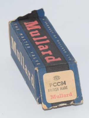
The PCC84 is a high-frequency double triode vacuum tube (valve) with separate cathodes, originally developed in the late 1950s for use in cascode RF amplifier stages of television and broadcast receivers. The tube was manufactured by several European companies, including Tesla (Czechoslovakia), Mullard (UK), Philips (Netherlands), Valvo (Germany), and others operating under the Philips/Mullard umbrella. The Tesla datasheet is dated March 2, 1959, placing the tube firmly in the golden era of European television tube development.
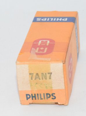
The "PCC" designation follows the Mullard–Philips Pro Electron naming convention: "P" indicates a 300 mA series heater string (designed for AC/DC television receivers), "CC" denotes a double triode, and "84" is the sequential type number. The tube was designed as a direct replacement for the 7AN7 (its American RETMA equivalent) and was also assigned the British military CV number CV5192.
The PCC84 was specifically engineered for low-noise VHF front-end applications. Triode I was intended as a grounded-cathode amplifier, while Triode II served as a grounded-grid amplifier in a cascode configuration — a topology that combined the low noise of a triode with the high gain and stability of a pentode. The two triode systems are independently shielded from each other by internal screening connected to the control grid of System II, a critical design feature for minimizing inter-stage coupling at VHF frequencies.
The PCC84 shares its electrical characteristics with the more common ECC84, which is its 6.3 V heater equivalent. The curves published in the Tesla datasheet are explicitly labeled as applicable to both the ECC84 and PCC84, confirming their identical internal electrode structures.
2. Technical Specifications and Design
General Construction
- Type: High-frequency double triode (Vysokofrekvenční dvojitá trioda)
- Envelope: All-glass miniature (celoskleněné miniaturní)
- Base: Noval (B9A), 9-pin miniature — Czech standard S 9/12 ČSN 35 8904
- Weight: Approximately 14 g
- Maximum envelope diameter: 22.2 mm
- Maximum seated height: 56.3 mm (from base reference plane)
- Internal shielding: Both systems are independently shielded; the internal shield is connected to the control grid of System II
- Cathode type: Indirectly heated, oxide-coated (nepřímé, katoda kysličníková)
Heater Ratings
| Parameter | Symbol | Value | Unit |
|---|---|---|---|
| Heater voltage | Uf | 7.2 | V |
| Heater current | If | 0.3 | A |
Note: The heater is rated at 7.2 V / 0.3 A per the Tesla datasheet, designed for 300 mA series heater strings in AC/DC television receivers. Some references round the heater voltage to 7 V.
Characteristic Values (per each triode system)
| Parameter | Symbol | Value | Unit |
|---|---|---|---|
| Anode voltage | Ua | 90 | V |
| Control grid bias | Ug1 | −1.5 | V |
| Anode current | Ia | 12 | mA |
| Transconductance (mutual conductance) | S (gm) | 6 | mA/V |
| Amplification factor | μ | 24 | — |
| Internal resistance (plate resistance) | Ri (rp) | 4 | kΩ |
Interelectrode Capacitances — System I (grounded cathode)
| Parameter | Symbol | Value | Unit |
|---|---|---|---|
| Input capacitance (grid-to-cathode) | Cg1 | 2.3 | pF |
| Output capacitance (anode-to-cathode) | Ca | 0.5 | pF |
| Feedthrough capacitance (grid-to-anode) | Cc/g1 | 1.1 | pF |
| Control grid to heater capacitance | Cg1/f | 0.25 | pF |
Interelectrode Capacitances — System II (grounded grid)
| Parameter | Symbol | Value | Unit |
|---|---|---|---|
| Cathode to grid+shield+heater | Ci/g1+s+f | 4.5 | pF |
| Cathode to heater | Cf/f | 2.5 | pF |
| Cathode to anode | Ck/a | 0.17 | pF |
| Anode to grid+shield | Ca/g1+s | 2.3 | pF |
Inter-System Capacitances
| Parameter | Symbol | Value | Unit |
|---|---|---|---|
| Grid I to anode II | Cg1I/aII | 0.006 | pF |
| Anode I to anode II | Ca/aII | 0.035 | pF |
| Anode I to cathode I + grid II + shield + heater | Ca/k1+f+g1II+s | 1.12 | pF |
Operating Values (Cascode Configuration)
| Parameter | Symbol | Value | Unit |
|---|---|---|---|
| Input resistance at 50 MHz | Rvst | 64 | kΩ |
| Input resistance at 100 MHz | Rvst | 16 | kΩ |
| Input resistance at 200 MHz | Rvst | 4 | kΩ |
| Noise figure | F | 6.5 | — |
Note: The above input resistance and noise figure values apply when the input circuit is connected to the input pin and the output circuit to the output pin, with the frame connected to chassis. When both cathode leads are connected in parallel, the noise figure reduces to F = 5 and the input resistance drops to Rvst = 1.4 kΩ.
Maximum Ratings (for both systems combined)
| Parameter | Symbol | Max Value | Unit |
|---|---|---|---|
| Anode voltage (cold, no signal) | Uao | 550 | V |
| Anode voltage (operating) | Ua | 180 | V |
| Anode dissipation (per section) | Wa | 2 | W |
| Anode dissipation (both sections combined) | WaI+aII | 3.5 | W |
| Cathode current (per section) | Ik | 18 | mA |
| External cathode-to-heater resistance | Rk/f | 20 | kΩ |
| Grid bias for grid current onset (Ig1 ≤ 0.3 μA) | Ug1i | −1.2 | V |
Maximum Ratings — System I
| Parameter | Symbol | Max Value | Unit |
|---|---|---|---|
| Grid leak resistance | Rg1I | 0.5 | MΩ |
| Cathode-to-heater voltage | Uk/f | 90 | V |
Maximum Ratings — System II
| Parameter | Symbol | Max Value | Unit |
|---|---|---|---|
| Grid leak resistance (Rk ≥ 100 Ω, bypassed) | Rg1II | 20 | kΩ |
| Grid leak resistance (bias from voltage divider) | Rg1II | 100 | kΩ |
| Cathode-to-heater voltage (DC component max 180 V) | U+k/f− | 250 | V |
| Cathode-to-heater voltage (negative direction) | U−k/f+ | 90 | V |
Pin Configuration (Noval B9A base, bottom view)
Based on the Tesla datasheet diagram:
- Pin 1: Anode II (aII)
- Pin 2: Grid I (g1I)
- Pin 3: Cathode I (input pin — klvst)
- Pin 4: Heater (f)
- Pin 5: Heater (f)
- Pin 6: Anode I (aI)
- Pin 7: Grid II (g1II)
- Pin 8: Cathode II (output pin — klvýst)
- Pin 9: Internal shield / screen (connected to grid II)
Note: The internal shield between the two triode systems is connected to the control grid of System II. All electrodes are brought out to the base pins.
3. Applications and Usage
The PCC84 was designed primarily for the following applications:
Cascode VHF/UHF Amplifier (Primary Application)
The tube's principal application was as a cascode RF amplifier in television and FM broadcast receiver front ends. In this configuration, Triode I operates as a grounded-cathode amplifier with the input signal applied to its grid, while Triode II operates as a grounded-grid amplifier with its cathode driven by the anode of Triode I. The grid of System II is grounded for RF via a bypass capacitor. This arrangement provides:
- Low noise figure (F = 6.5 in standard configuration, reducible to F = 5 with paralleled cathodes)
- High effective gain comparable to a pentode stage
- Excellent stability due to the extremely low inter-system capacitances (grid I to anode II: only 0.006 pF)
- Good input resistance at VHF frequencies (64 kΩ at 50 MHz, 16 kΩ at 100 MHz)
Series Heater String Operation
The 300 mA / 7.2 V heater rating made the PCC84 ideal for AC/DC television receivers that used series-connected heater strings without a power transformer. This was a common and cost-effective design approach in European television sets of the 1950s and 1960s.
Application Circuits
The Tesla datasheet provides two reference circuits for the cascode configuration, both operating from a +180 V supply:
- Circuit 1: Uses a 10 kΩ anode load resistor for Triode II, with a 120 Ω / 150 pF cathode bias network for Triode I.
- Circuit 2: Uses a voltage divider network (100 kΩ / 100 kΩ / 100 kΩ) to establish the operating point for Triode II.
4. Sound Characteristics
While the PCC84 was designed as an RF tube rather than an audio amplifier, its electrical characteristics give it a distinctive sonic signature when pressed into audio service:
Tonal Character
The PCC84, like its 6.3 V sibling the ECC84, is a medium-mu triode (μ = 24) with relatively high transconductance (6 mA/V) and low plate resistance (4 kΩ). This combination produces a sound that is often described as:
- Clean and articulate: The relatively low amplification factor compared to high-mu types like the ECC83/12AX7 (μ = 100) means less gain per stage but also less tendency toward harmonic distortion buildup. The sound is clear and uncolored at moderate signal levels.
- Dynamic and punchy: The high transconductance and low plate resistance give the tube excellent current delivery capability, resulting in a lively, dynamic presentation with good transient response.
- Slightly lean in the midrange: Compared to warmer-sounding medium-mu triodes like the 12AU7/ECC82 (which has a similar mu of ~20 but different internal geometry), the PCC84 can sound slightly more analytical and less "tubey." This is partly attributable to its RF-optimized electrode structure with tight spacing.
- Extended high frequencies: Being designed for VHF operation, the PCC84 has excellent high-frequency response characteristics. In audio circuits, this translates to an open, airy top end with good detail retrieval.
- Low microphonics: The miniature all-glass construction with well-supported electrode structures typically results in low microphonic sensitivity, which is beneficial in high-gain audio applications.
Harmonic Distortion Profile
As a triode, the PCC84 produces predominantly even-order harmonics (primarily second harmonic), which are generally perceived as musically pleasant. The Tesla datasheet includes distortion curves showing that at Ua = 90 V, distortion remains moderate across a wide range of operating currents. The relatively high transconductance means the tube can deliver good linearity when properly biased.
Noise Performance
The PCC84 was specifically designed for low-noise RF applications, with a noise figure of 6.5 (or 5 with paralleled cathodes). This low-noise heritage makes it a quiet tube in audio circuits, with low hiss and hum levels when properly implemented with appropriate heater-to-cathode voltage management.
5. Equivalent and Substitute Types
Direct Equivalents
| Type | Relationship | Notes |
|---|---|---|
| 7AN7 | Direct equivalent (RETMA designation) | American designation for the same tube. Identical pinout and specifications. Fully interchangeable. |
| CV5192 | Direct equivalent (British military) | British military designation. Identical specifications, may have tighter selection tolerances. |
| 30L1 | Equivalent (noted in Tesla datasheet) | Listed by Tesla as a foreign equivalent type. |
Related Types (Not Direct Substitutes)
| Type | Relationship | Key Difference |
|---|---|---|
| ECC84 | 6.3 V heater equivalent | Identical internal structure and electrical characteristics, but heater rated at 6.3 V / 0.34 A instead of 7.2 V / 0.3 A. NOT a drop-in replacement — heater voltage difference requires circuit modification. Shares the same published characteristic curves. |
| ECC85 | Related type, different characteristics | Also a double triode for VHF, but with different electrical parameters. Not interchangeable. |
Important: The PCC84 and ECC84 are electrically identical in their triode sections but differ in heater requirements. The PCC84's 7.2 V / 300 mA heater is designed for series heater strings, while the ECC84's 6.3 V heater is for parallel heater circuits. Substituting one for the other requires appropriate heater supply modification.
6. Notable Characteristics
Exceptional Inter-System Isolation
One of the PCC84's most remarkable specifications is the extraordinarily low capacitance between the two triode systems. The grid I to anode II capacitance is only 0.006 pF, and the anode I to anode II capacitance is just 0.035 pF. This level of isolation is achieved through the internal shielding connected to the grid of System II, and it is what makes the cascode configuration so effective at VHF frequencies.
High Cold Anode Voltage Rating
The PCC84 can withstand up to 550 V on the anode when cold (no current flowing), despite having a maximum operating anode voltage of only 180 V. This generous cold rating provides excellent reliability margins during equipment warm-up and in circuits where transient voltage spikes may occur.
Asymmetric System Usage
Unlike many dual triodes where both sections are used identically, the PCC84 was designed with the explicit intention that the two triode systems would serve different functions. System I (grounded cathode) and System II (grounded grid) have different maximum grid leak resistance ratings (0.5 MΩ vs. 20–100 kΩ) and different cathode-to-heater voltage limits (90 V vs. 250 V), reflecting their different roles in the cascode circuit.
Frequency-Dependent Input Resistance
The Tesla datasheet provides detailed input resistance data across frequency, showing how the tube's input loading changes dramatically with frequency: from 64 kΩ at 50 MHz down to just 4 kΩ at 200 MHz. This information was critical for RF circuit designers who needed to match antenna impedances and design input coupling networks.
Comprehensive Characteristic Curves
The Tesla datasheet includes an unusually complete set of characteristic curves: Ia = f(Ug1) transfer characteristics, Ia = f(Ua) plate characteristics, S/D/μ/Ri/Ug1 = f(Ia) composite curves, S = f(Ug1) transconductance curves, S and −Ug1 and Ia = f(Ua) combined operating curves, and cascode transfer characteristics for both reference circuits.
7. Usage in the Audio Community
Historical Context
The PCC84 was never intended as an audio tube, and it does not appear in any classic audio amplifier designs from the golden age of hi-fi. However, the modern audio community's insatiable appetite for experimenting with unusual tube types has brought the PCC84 into the audio world, particularly as stocks of more popular audio tubes become scarce and expensive.
DIY Audio Applications
In the DIY audio community, the PCC84 (and its ECC84 equivalent) has found use in several applications:
- Line-stage preamplifiers: The μ of 24 and low plate resistance of 4 kΩ make the PCC84 suitable for line-stage designs where moderate gain and good driving capability are needed. It can drive long interconnect cables and low-impedance loads more effectively than high-mu, high-impedance types.
- Phono preamplifier stages: The low noise characteristics inherited from its RF heritage make the PCC84 an interesting candidate for phono stages, though its moderate gain means multiple stages may be required for moving-coil cartridges.
- Cathode follower / buffer stages: The high transconductance and low plate resistance make the PCC84 an excellent cathode follower, providing low output impedance and good current delivery for driving headphones or subsequent amplifier stages.
- Driver stages for power amplifiers: The PCC84's ability to deliver relatively high current with low distortion makes it suitable as a driver for push-pull power output stages.
- SRPP (Shunt Regulated Push-Pull) circuits: The dual triode configuration is naturally suited to SRPP topology, where both sections work together to provide improved linearity and output drive capability.
Headphone Amplifiers
The PCC84's characteristics — moderate gain, low output impedance, high transconductance, and low noise — make it particularly well-suited for headphone amplifier designs. Several DIY headphone amplifier projects have been published using the ECC84/PCC84, taking advantage of the tube's ability to drive the relatively low impedances of modern headphones.
Availability and Pricing
The PCC84 remains relatively available on the NOS (New Old Stock) market, as large quantities were manufactured for the television industry. Mullard (UK), Tesla (Czechoslovakia), Philips (Netherlands), Valvo (Germany), Siemens, and other manufacturers all produced this type. Because it is not a "mainstream" audio tube, prices tend to be significantly lower than equivalent audio-grade types like the ECC82 or ECC83, making it an attractive option for budget-conscious audio experimenters.
Practical Considerations for Audio Use
When using the PCC84 in audio circuits, several practical points should be noted:
- Heater supply: The 7.2 V / 300 mA heater requires a dedicated supply or appropriate series resistor if powered from a standard 6.3 V or 12.6 V winding. DC heater supplies are recommended for lowest noise in audio applications.
- Cathode-to-heater voltage: The maximum cathode-to-heater voltage limits (90 V for System I, 250 V for System II) must be respected. In audio circuits with elevated cathode voltages, this may require a heater supply referenced to a positive DC voltage.
- Operating point selection: The Tesla datasheet's characteristic curves (shared with the ECC84) provide excellent guidance for selecting operating points. The composite curve showing S, D, μ, Ri, and Ug1 as functions of Ia at Ua = 90 V is particularly useful for audio design optimization.
- Maximum plate dissipation: The 2 W per section limit (3.5 W total for both sections) must be observed. At the typical audio operating point of Ua = 90 V and Ia = 12 mA, the plate dissipation is approximately 1.08 W per section, well within limits.
- Interchangeability with ECC84: For audio applications, the ECC84 is generally more convenient due to its standard 6.3 V heater. The two types are electrically identical in their triode sections, so any audio circuit designed for one can use the other with only a heater supply change.
Manufacturer Preferences
Among audio enthusiasts who use the PCC84/ECC84, Mullard-manufactured examples are generally the most sought-after, consistent with the broader audiophile preference for Mullard tubes. Tesla-manufactured PCC84s are also well-regarded and tend to offer excellent value. Philips/Amperex and Valvo examples are considered comparable to Mullard in quality. As with all NOS tubes, individual specimen variation can be significant, and matched pairs should be sought for balanced circuit applications.