Introduction and History
The PCL84 is a compound (combined) triode-pentode vacuum tube designed primarily for television receiver applications. Developed in the late 1950s, with manufacturer datasheets dating from April 12, 1960, the PCL84 was conceived as a versatile dual-section valve that could serve multiple functions within a single envelope. The tube was classified as a "Televizní Trioda – Pentoda" (Television Triode-Pentode) in its original Czech/European documentation.
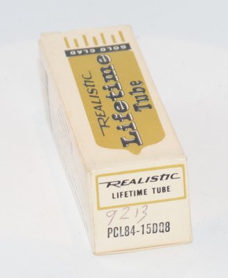
The PCL84 belongs to the European "P" heater series, designed for series-string heater operation at 15 volts — a common configuration in European television sets that derived heater power directly from the mains supply through series-connected filaments. Its American equivalent is the 15DQ8, sharing the same electrical characteristics but following RETMA naming conventions.
The tube was originally intended for two specific functions in television circuits: the triode section was designed for sync separator or amplifier stages handling synchronization pulses, while the pentode section was intended as the video output (picture amplifier) stage. This combination of a small-signal triode with a medium-power pentode in a single envelope allowed television manufacturers to reduce chassis size, component count, and cost — critical factors in the competitive consumer electronics market of the early 1960s.
The PCL84 was manufactured by numerous European valve makers including Philips/Mullard, Valvo, Amperex, Tesla, Tungsram, and others. The tube features an all-glass miniature construction with a Noval (9-pin) base, and the suppressor grid (g3) of the pentode section is internally connected to the cathode of the pentode — notably, the two sections have separate cathodes, providing important circuit design flexibility.
Technical Specifications and Design
General Data
| Parameter | Value |
|---|---|
| Tube Type | Triode-Pentode (compound) |
| Base | Noval (B9A) — 9-pin miniature |
| Envelope | All-glass miniature |
| Mounting | Any position |
| Weight | Max 16 g |
| Socket | S 9/12 ČSN 35 8904 |
Heater Data
| Parameter | Symbol | Value |
|---|---|---|
| Heater Voltage | Uf | 15 V |
| Heater Current | If | 300 mA |
| Heating | Indirect, oxide-coated cathode, series or AC/DC operation | |
Interelectrode Capacitances — Pentode Section
| Parameter | Symbol | Value |
|---|---|---|
| Input Capacitance | Cg1 | 9 pF |
| Output Capacitance | Ca | 4.5 pF |
| Feedback Capacitance (grid-to-anode) | Ca/g1 | 0.01 pF max |
Interelectrode Capacitances — Triode Section
| Parameter | Symbol | Value |
|---|---|---|
| Input Capacitance | Cg1 | 4.0 pF |
| Output Capacitance | Ca | 2.3 pF (datasheet) / 2.5 pF (TDSL) |
| Feedback Capacitance (grid-to-anode) | Ca/g1 | 2.7 pF |
| Grid-to-heater Capacitance | Cg1/f | 0.045 pF min / 0.1 pF max |
Inter-System Capacitances
| Parameter | Symbol | Value |
|---|---|---|
| Triode Anode to Pentode Control Grid | CaT/g1P | 0.01 pF max |
| Triode Grid to Pentode Control Grid | Cg1T/g1P | 0.01 pF max |
Characteristic Data — Pentode Section
| Parameter | Symbol | 170 V | 200 V | 220 V |
|---|---|---|---|---|
| Anode Voltage | Ua | 170 V | 200 V | 220 V |
| Screen Grid Voltage | Ug2 | 170 V | 200 V | 220 V |
| Control Grid Voltage | Ug1 | −2.1 V | −2.9 V | −3.4 V |
| Anode Current | Ia | 18 mA | 18 mA | 18 mA |
| Screen Grid Current | Ig2 | 3 mA | 3 mA | 3 mA |
| Transconductance | S | 11 mA/V | 10.4 mA/V | 10 mA/V |
| Screen Grid Amplification Factor | μg2/g1 | ~36 | 36 | 36 |
| Internal Resistance | Ri | >100 kΩ | >130 kΩ | >150 kΩ |
| Anode Cutoff Current (Ug1 = −8 V) | Iaz | — | <1.3 mA | — |
Characteristic Data — Triode Section
| Parameter | Symbol | Value |
|---|---|---|
| Anode Voltage | Ua | 200 V |
| Control Grid Voltage | Ug1 | −1.7 V |
| Anode Current | Ia | 3 mA |
| Transconductance | S (gm) | 4.0 mA/V |
| Amplification Factor | μ | 65 |
| Plate Resistance | Ri | ~16,200 Ω (calculated: μ/gm = 65/4.0 = 16,250 Ω) |
| Anode Cutoff Current (Ug1 = −4 V) | Iaz | <0.6 mA |
Operating Values — Pentode as Video Output Stage
| Parameter | Symbol | 170 V | 200 V | 220 V |
|---|---|---|---|---|
| Supply Voltage | Ub | 170 V | 200 V | 220 V |
| Anode Load Resistance | Ra | 3 kΩ | 3 kΩ | 3 kΩ |
| Screen Grid Voltage | Ug2 | 170 V | 200 V | 220 V |
| Control Grid Voltage | Ug1 | −2 V | −2.8 V | −3.3 V |
| Anode Current | Ia | 18 mA | 18 mA | 18 mA |
| Screen Grid Current | Ig2 | 3.2 mA | 3.1 mA | 3.1 mA |
| Transconductance | S | 10.4 mA/V | 10 mA/V | 9.7 mA/V |
Maximum Ratings — Pentode Section
| Parameter | Symbol | Value |
|---|---|---|
| Anode Voltage (cold) | Ua0 | 550 V max |
| Anode Voltage (operating) | Ua | 250 V max |
| Anode Dissipation | Wa | 4 W max |
| Screen Grid Voltage (cold) | Ug2,0 | 550 V max |
| Screen Grid Voltage (operating) | Ug2 | 250 V max |
| Screen Grid Dissipation | Wg2 | 1.7 W max |
| Cathode Current | Ik | 40 mA max |
| Grid Resistor (fixed bias) | Rg1 | 1 MΩ max |
| Grid Resistor (cathode bias) | Rg1 | 2 MΩ max |
| Cathode-to-Heater Voltage | Uk/f | 200 V max |
| External Cathode-to-Heater Resistance | Rk/f | 20 kΩ max |
| Grid Voltage for Positive Grid Current Onset (Ig1 = +0.3 μA) | −Ug1i | 1.3 V max |
Maximum Ratings — Triode Section
| Parameter | Symbol | Value |
|---|---|---|
| Anode Voltage (cold) | Ua0 | ±550 V max |
| Anode Voltage (operating) | Ua | ±250 V max |
| Anode Voltage (peak, Ia < 0.1 mA) | Ua,sp | 600 V max |
| Anode Dissipation | Wa | 1 W max |
| Cathode Current | Ik | 12 mA max |
| Grid Resistor (fixed bias) | Rg1 | 1 MΩ max |
| Grid Resistor (cathode bias) | Rg1 | 3 MΩ max |
| Cathode-to-Heater Voltage | Uk/f | 150 V max |
| External Cathode-to-Heater Resistance | Rk/f | 20 kΩ max |
| Grid Voltage for Positive Grid Current Onset (Ig1 = +0.3 μA) | −Ug1i | 1.3 V max |
Important Design Note
The suppressor grid (g3) of the pentode section is internally connected to the cathode of the pentode. The two sections (triode and pentode) have separate, independent cathodes. This is a critical consideration for circuit design, as it allows each section to operate with its own cathode bias arrangement and prevents unwanted interaction between the two sections through a shared cathode impedance.
Pin Configuration (Noval B9A Base — Bottom View)
Based on the datasheet diagram, the pin assignments are:
| Pin | Connection |
|---|---|
| 1 | Pentode Anode (aP) |
| 2 | Pentode Screen Grid g2 (g2P) |
| 3 | Pentode Control Grid g1 (g1P) |
| 4 | Heater / Filament |
| 5 | Heater / Filament |
| 6 | Triode Anode (aT) |
| 7 | Triode Grid (gT) |
| 8 | Triode Cathode (kT) |
| 9 | Pentode Cathode (kP) — internally connected to pentode g3 and screen |
Note: Pin assignments should be confirmed against the specific manufacturer's datasheet for the production variant being used, as some sources may differ slightly in pin labeling conventions.
Applications and Usage
Original Television Applications
The PCL84 was designed specifically for European television receivers and found widespread use in the following configurations:
Triode Section
- Sync Separator: The triode's moderate amplification factor (μ = 65) and low anode current (3 mA) made it well-suited for extracting synchronization pulses from the composite video signal. The separate cathode allowed optimal biasing for sync clipping.
- Sync Amplifier: Used to amplify synchronization pulses before feeding them to the timebase oscillators.
- AGC (Automatic Gain Control) Keying: The triode section could serve as a keyed AGC detector in some circuit configurations.
Pentode Section
- Video Output Stage: This was the primary intended application. With a transconductance of 10 mA/V, anode current of 18 mA, and 4 W maximum anode dissipation, the pentode could drive a CRT (cathode ray tube) directly. The typical operating point used a 3 kΩ anode load resistor with supply voltages from 170 V to 220 V.
- IF Amplifier: In some designs, the pentode section was used as an intermediate frequency amplifier stage, taking advantage of its high transconductance and high internal resistance (>150 kΩ at 220 V).
Pulse Operation Note
The datasheet specifies that pulse duration should not exceed 18% of the period and no longer than 18 μs — a specification directly related to the video output application where the tube must handle line-rate video signals.
General Amplifier Applications
Beyond television, the PCL84's combination of a medium-μ triode and a high-transconductance pentode made it suitable for various general-purpose amplification tasks, including:
- Two-stage audio preamplifiers (triode as first stage, pentode as second)
- Combined preamplifier and output stage in small audio amplifiers
- Instrument amplifiers
- Signal processing circuits requiring both voltage amplification and power gain
Sound Characteristics
The PCL84 has developed a modest but dedicated following among audio enthusiasts, particularly those who enjoy experimenting with unconventional tubes. Its sonic character varies significantly depending on which section is employed and how it is configured:
Triode Section Sound
The triode section of the PCL84, with its amplification factor of 65 and transconductance of 4.0 mA/V, produces a sound that is generally described as:
- Clean and articulate: The moderate μ of 65 places it between low-μ triodes (like the 6SN7) and high-μ types (like the 12AX7). This results in a balanced presentation that is neither overly warm nor clinically detailed.
- Slightly lean in the midrange: Compared to dedicated audio triodes, the triode section can sound somewhat thinner, reflecting its television heritage where bandwidth was prioritized over tonal richness.
- Good transient response: The relatively low interelectrode capacitances (Cgk = 4.0 pF, Cga = 2.7 pF) contribute to crisp transient handling and extended high-frequency response.
- Low noise floor: When properly implemented with appropriate heater-cathode voltage management, the triode section can achieve respectably low noise levels suitable for phono or microphone preamplifier stages.
Pentode Section Sound
The pentode section, with its high transconductance of 10 mA/V and 4 W anode dissipation, offers a different sonic character:
- Dynamic and punchy: The high gm provides excellent signal handling capability and dynamic contrast, giving the pentode section a lively, energetic quality.
- Extended bandwidth: Originally designed for video frequencies, the pentode section naturally delivers wide bandwidth audio reproduction with excellent high-frequency extension.
- Characteristic pentode brightness: Like most pentodes, the PCL84's pentode section tends toward a brighter, more forward tonal balance compared to triode operation. This can be tamed through ultralinear or triode-strapped configurations.
- Modest power output: With only 4 W maximum anode dissipation, single-ended output power is limited to approximately 1–1.5 W in Class A, making it suitable for high-efficiency speaker systems or headphone amplifiers.
Overall Sonic Assessment
The PCL84 is not typically regarded as a top-tier audio tube, but it can deliver surprisingly musical results in well-designed circuits. Its sound is often characterized as honest, detailed, and slightly forward — qualities that some listeners find refreshing compared to the more romanticized sound of classic audio tubes. The combination of both sections in a single envelope allows for compact, cost-effective designs that can produce engaging sound quality, particularly in headphone amplifiers and low-power single-ended designs paired with efficient loudspeakers.
Equivalent and Substitute Types
| Type | Relationship | Notes |
|---|---|---|
| 15DQ8 | Direct American equivalent | Identical electrical specifications and pinout. Full drop-in replacement. |
| ECL84 | Electrically similar, different heater | The ECL84 is the 6.3 V heater version (6.3 V at 660 mA). Electrically equivalent sections but NOT a direct substitute due to different heater voltage. Can be used in new designs where 6.3 V heater supply is available. |
| PCL84 variants | Manufacturer equivalents | Produced by Philips, Mullard, Valvo, Amperex, Tesla, Tungsram, RFT, and others. All are interchangeable. |
Important: The PCL84 should not be confused with the PCL82 or PCL86, which are also triode-pentode combinations but have different electrical characteristics, different pinouts, and are not interchangeable. The PCL82 has a lower-transconductance pentode section, while the PCL86 was designed specifically for audio output applications with different operating parameters.
Notable Characteristics
Separate Cathodes
One of the most significant design features of the PCL84 is its separate cathodes for the triode and pentode sections. This provides several advantages:
- Independent biasing of each section without interaction
- No shared cathode impedance that could cause unwanted feedback or signal coupling
- Greater flexibility in circuit design, allowing each section to operate at its optimal bias point
- Reduced crosstalk between sections
Internal Suppressor Grid Connection
The pentode's suppressor grid (g3) is internally connected to the pentode cathode. This is standard practice for most receiving pentodes but is worth noting for circuit designers who might otherwise attempt an external connection.
High Cold Voltage Rating
Both sections can withstand remarkably high voltages when cold (no heater current flowing): 550 V for the pentode anode and screen grid, and ±550 V for the triode anode. This provides a generous safety margin during power supply turn-on transients in series-heater television circuits where the HT supply may reach full voltage before the heaters warm up.
Excellent Screening Between Sections
The inter-system capacitances are extremely low — both the triode anode-to-pentode grid and triode grid-to-pentode grid capacitances are specified at a maximum of only 0.01 pF. This excellent internal screening minimizes unwanted coupling between the two sections, which was essential for the tube's television applications where the sync separator and video output stages operated in close proximity.
High Pentode Transconductance
The pentode section's transconductance of 10–11 mA/V is notably high for a tube of this size and power rating, reflecting its video amplifier heritage where wide bandwidth and high gain were paramount. This high gm makes the pentode section particularly effective as a voltage amplifier or driver stage.
Screen Grid Amplification Factor
The pentode's screen grid amplification factor (μg2/g1) of 36 is a useful parameter for calculating stage gain and for designing screen grid supply circuits. This value remains consistent across the full range of operating voltages (170–220 V).
Usage in the Audio Community
Headphone Amplifiers
The PCL84 has found its most enthusiastic audio following in the headphone amplifier community. The combination of a triode voltage amplifier and pentode output stage in a single envelope makes it ideal for compact headphone amp designs. Typical configurations include:
- Triode input / Pentode output: The triode section provides voltage gain while the pentode section, operating in Class A single-ended, drives headphones through an output transformer. With careful design, output power of 0.5–1.5 W can be achieved — more than sufficient for most headphones.
- Triode-strapped pentode output: Some designers connect the pentode section as a triode (screen grid tied to anode) for a warmer, more linear sound at the expense of some output power and gain.
Low-Power Single-Ended Amplifiers
DIY audio enthusiasts have built single-ended amplifiers using the PCL84, typically producing 1–2 watts per channel. These designs are paired with high-efficiency loudspeakers (95+ dB sensitivity) and are valued for their simplicity — a complete amplifier channel can be built with a single PCL84 tube. The pentode section's 4 W maximum anode dissipation and 18 mA operating current provide adequate headroom for small SE designs.
Preamplifier Applications
The triode section, with its μ of 65 and gm of 4.0 mA/V, has been used in line-stage and phono preamplifier circuits. Its plate resistance of approximately 16,200 Ω is low enough to drive reasonable cable capacitances, and the moderate gain is suitable for line-level signal processing. Some builders use both sections as cascaded gain stages in phono preamplifiers, taking advantage of the excellent inter-section screening.
Guitar Amplifier Experimentation
A small number of guitar amplifier builders have experimented with the PCL84, particularly for practice amplifiers and recording setups where low power output is desirable. The pentode section's video-amplifier lineage gives it a fast, responsive character that some players find appealing for clean tones, while the limited headroom produces natural compression and breakup at very low volumes.
Availability and Cost
The PCL84 / 15DQ8 remains relatively available as NOS (New Old Stock) at moderate prices, as it was produced in very large quantities for the television market. This affordability, combined with the tube's versatility, makes it an attractive option for experimenters and budget-conscious audio builders. Gold-pin premium versions from various manufacturers are also available for those seeking the highest quality specimens. Because the PCL84 was never a mainstream audio tube, NOS stocks have not been depleted by high demand, and good-quality examples can still be found from European and American sources.
Design Considerations for Audio Use
When using the PCL84 in audio circuits, designers should keep the following points in mind:
- Heater supply: The 15 V / 300 mA heater requires either a dedicated 15 V winding on the power transformer or a DC heater supply. Series-string operation with other 300 mA tubes is also possible. For lowest noise in audio applications, DC heater supplies are recommended.
- Cathode-heater voltage: The maximum cathode-to-heater voltage is 200 V for the pentode and 150 V for the triode. In circuits with elevated cathode voltages, this limit must be respected.
- Separate cathodes: The independent cathodes allow each section to be biased optimally without compromise, but designers must provide separate cathode bias networks.
- Screen grid supply: For the pentode section in audio service, a well-filtered, low-impedance screen grid supply is essential for good performance. The 1.7 W maximum screen dissipation must not be exceeded.