1. Introduction and History
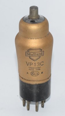
The Mullard VP13C is a variable-mu (remote cutoff) high-frequency pentode valve designed for use in D.C./A.C. mains-operated receivers and car radios. Manufactured by Mullard, one of Britain's most respected valve producers, the VP13C belongs to the Mullard 13-volt heater series — a family of valves specifically engineered for automotive and battery-eliminator applications where a 13-volt heater supply was standard.
The "VP" designation in Mullard's nomenclature indicates a Variable-mu Pentode, while the "13" refers to the 13.0-volt heater voltage, and the "C" suffix denotes a particular iteration or base type within the series. This valve emerged during the late 1930s, a period when car radio was becoming increasingly popular and manufacturers needed valves that could operate reliably from the 12-volt (nominal) electrical systems found in automobiles of the era. The 13-volt heater rating allowed direct operation from a car battery with minimal series resistance, simplifying receiver design considerably.
The variable-mu characteristic was essential for its intended role as an RF or IF amplifier stage, as it allowed smooth automatic gain control (AGC) without the cross-modulation distortion that would occur with sharp-cutoff pentodes under strong-signal conditions. The VP13C uses a metallised glass envelope and a 7-pin base with a top cap connection for the control grid (G4), a common arrangement for RF valves of this period that minimised stray capacitance between the input and output circuits.
2. Technical Specifications and Design
Heater Characteristics
| Heater Voltage (Vf) | 13.0 volts |
| Heater Current (If) | 0.2 amp |
| Heating Time | 60 seconds |
Operating Characteristics (Normal Conditions)
| Normal Anode Voltage (Vaw) | 200 volts |
| Normal Auxiliary Grid Voltage (Vg2w) | 200 volts |
| Anode Current (Iaw) | 9.0 mA |
| Auxiliary Grid Current (Ig2w) | 3.6 mA |
| Control Grid Voltage at Ia = 9.0 mA (−Vg1w) | 2.0 volts |
| Mutual Conductance (Sw) at −Vg1 = 2.0 volts | 2.2 mA/V |
Interelectrode Capacitances
| Anode–Control Grid (Cag1) | 0.0023 µµF (pF) |
| Output Capacitance (Ca) | 8.0 µµF (pF) |
| Input Capacitance (Cg1) | 6.1 µµF (pF) |
Absolute Maximum Ratings (Limits)
| Maximum Anode Voltage (Vamax) | 200 volts |
| Maximum Anode Dissipation (Wamax) | 2.5 watts |
| Maximum Auxiliary Grid Voltage (Vg2max) | 200 volts |
| Maximum Auxiliary Grid Dissipation (Wg2max) | 0.7 watt |
| Maximum Resistance Heater to Cathode (Rfk) | 20,000 ohms |
| Maximum Voltage Heater to Cathode (Vfk) | 125 volts |
| Maximum Resistance in Grid Circuit (Rg1max) | 2.5 megohms |
| Range of Grid Voltage for 1 µA Grid Current (Vg1) | −0.1 to −0.7 volt |
Physical Dimensions
| Overall Length | 126 mm |
| Overall Diameter | 43 mm |
| Bulb Finish | Metallised |
| Base Type | 7-pin (with top cap) |
Pin Connections (Viewed from Free End of Pins)
| Pin | Connection |
|---|---|
| 1 | Metallising |
| 2 | Anode |
| 3 | Suppressor Grid (G3) |
| 4 | Heater |
| 5 | Heater |
| 6 | Cathode |
| 7 | Auxiliary Grid (G2 — Screen Grid) |
| Top Cap | Control Grid (G4) |
Note: In Mullard's nomenclature for this valve, the control grid is designated G4 and is brought out to the top cap to minimise input-to-output capacitance, which is critical for stable RF amplification. The extremely low anode-to-control-grid capacitance of just 0.0023 pF reflects the effectiveness of this arrangement.
Derived Parameters
From the published data, the mutual conductance (transconductance, gm) is 2.2 mA/V at the normal operating point. The amplification factor (µ) and plate resistance (rp) are not explicitly stated in the available Mullard datasheet. However, given the typical characteristics of variable-mu RF pentodes of this class, the plate resistance would be expected to be in the range of several hundred kilohms, and the amplification factor correspondingly high. These values should be confirmed against a complete manufacturer datasheet if precise figures are required for design work.
3. Applications and Usage
The Mullard VP13C was designed primarily for the following applications:
RF and IF Amplification in Car Radios
The VP13C's principal application was as a radio-frequency (RF) or intermediate-frequency (IF) amplifier in car radio receivers. Its 13-volt heater allowed direct operation from the vehicle's 12-volt battery system (which typically runs at 12.6–13.8 volts when the engine is running and the dynamo/alternator is charging). This eliminated the need for heater voltage dropping resistors or complex power supply arrangements.
Variable-Mu AGC Operation
The remote-cutoff (variable-mu) characteristic of the VP13C made it ideal for use in circuits employing automatic gain control (AGC). As the AGC voltage increased (became more negative), the tube's gain decreased smoothly and progressively, preventing the sudden cutoff and associated distortion that would occur with a sharp-cutoff pentode. This was particularly important in car radio applications where signal strength could vary dramatically as the vehicle moved through different reception areas.
D.C./A.C. Mains Receivers
Beyond car radio use, the VP13C also found application in mains-operated receivers designed for universal (D.C./A.C.) operation. In series-heater chains for such receivers, the 13-volt, 0.2-amp heater rating made it compatible with other valves in the Mullard 0.2-amp series.
Military and Government Use
The VP13C was assigned the CV (Common Valve) designation CV3790 for British military and government procurement purposes, indicating that it saw use in military communications equipment and other government applications where standardised valve types were required.
4. Sound Characteristics
While the VP13C was designed as an RF/IF amplifier rather than an audio-frequency amplifier, its sonic characteristics are relevant when it is repurposed or evaluated in audio contexts:
General Tonal Character
Variable-mu pentodes of this era and class tend to exhibit a warm, smooth tonal character when used in audio circuits. The VP13C, with its relatively modest transconductance of 2.2 mA/V, does not have the aggressive, high-gain character of later miniature pentodes. Instead, it offers a gentler, more rounded amplification that many listeners find pleasing.
Distortion Characteristics
The variable-mu grid structure means that as signal levels increase, the tube transitions gradually into compression rather than clipping abruptly. This produces a soft, musical form of distortion that is harmonically rich — predominantly even-order harmonics at moderate overdrive levels, transitioning to a mix of even and odd harmonics at higher levels. This "soft clipping" behaviour is one reason why variable-mu pentodes are sometimes favoured in certain audio applications, particularly in guitar amplifier and effects contexts.
Noise Performance
As an RF pentode, the VP13C was designed with attention to low-noise performance, which translates well to audio use. The metallised envelope provides effective shielding against external interference. However, being a pentode, it will inherently exhibit more partition noise (caused by the division of current between screen grid and anode) than a triode, which can manifest as a slightly higher noise floor in very quiet audio circuits.
Dynamic Response
The VP13C's variable-mu characteristic gives it a naturally dynamic, expressive quality. At low signal levels, the full transconductance is available, providing crisp, detailed amplification. As signal levels rise, the gradual gain reduction creates a natural compression effect that can add body and sustain to musical signals without sounding harsh or artificial.
Frequency Response
Designed for high-frequency RF work, the VP13C has excellent high-frequency response characteristics. The low interelectrode capacitances (particularly the remarkably low 0.0023 pF anode-to-grid capacitance) ensure minimal Miller effect and extended bandwidth, which in audio applications translates to an open, airy top end without the roll-off sometimes associated with audio-specific valves.
5. Equivalent or Substitute Types
| Type | Relationship | Notes |
|---|---|---|
| CV3790 | Direct equivalent (military designation) | Identical valve under the British military Common Valve numbering system. Fully interchangeable with no differences in specifications or pinout. |
Important Notes on Substitution:
- The VP13C's 13.0-volt, 0.2-amp heater is relatively unusual and limits direct substitution with more common valve types. Most RF pentodes of similar electrical characteristics use different heater voltages (e.g., 6.3V or 4V), making them unsuitable as drop-in replacements without heater circuit modifications.
- The 7-pin base with top cap connection further restricts substitution options, as the physical socket and wiring must match.
- Other Mullard variable-mu pentodes such as the VP4B (4-volt heater) or VP2B (2-volt heater) share similar electrical characteristics in terms of anode voltage and screen voltage ratings, but differ in heater requirements and may differ in base configuration. These are not direct substitutes without circuit modification.
- If other direct equivalents exist beyond CV3790, they should be confirmed against comprehensive cross-reference databases, as the author cannot verify additional substitutes with full confidence.
6. Notable Characteristics
Exceptionally Low Anode-to-Grid Capacitance
The VP13C achieves an anode-to-control-grid capacitance of just 0.0023 pF — an extraordinarily low figure that speaks to the effectiveness of the top-cap grid connection and internal shielding. This made the valve highly stable in RF amplifier circuits, virtually eliminating the risk of oscillation due to feedback through the valve's internal capacitance.
Metallised Envelope
The metallised glass bulb serves as an electrostatic shield, connected to pin 1 and typically grounded in the circuit. This provides excellent screening against external electric fields and reduces hum pickup — a valuable feature in both RF and audio applications.
13-Volt Heater Series
The 13-volt heater is a distinctive feature that places the VP13C firmly in the car radio category. While this limits its versatility compared to 6.3-volt types, it makes the valve uniquely suited to its intended application. The 0.2-amp heater current means the heater consumes only 2.6 watts — an important consideration in battery-powered equipment.
Generous Grid Resistance Allowance
The maximum allowable grid circuit resistance of 2.5 megohms is notably generous, allowing the use of high-value grid resistors in AGC circuits without risk of grid current-related problems. This simplified AGC circuit design in receivers.
60-Second Heating Time
The specified 60-second heating time is typical for indirectly heated valves of this era and should be accounted for in circuit design — particularly in car radio applications where users expected relatively quick warm-up times.
High Heater-to-Cathode Voltage Rating
The 125-volt maximum heater-to-cathode voltage rating is substantial and allows the VP13C to be used in series-heater chains where significant voltage differences may exist between the heater and cathode circuits, as is common in AC/DC universal receiver designs.
7. Usage in the Audio Community
Vintage Radio Restoration
The most common audio-related use of the VP13C today is in the restoration and maintenance of vintage car radios and AC/DC mains receivers from the late 1930s and 1940s. Collectors and restorers of period-correct car radios — particularly those fitted to British vehicles of the era — seek out VP13C valves to maintain originality. The CV3790 military equivalent is often used as a more readily available substitute in these restorations.
Experimental Audio Projects
A small but dedicated community of audio experimenters and DIY valve amplifier builders occasionally use the VP13C in experimental audio circuits. Its variable-mu characteristic makes it interesting for:
- Voltage-controlled amplifiers (VCAs): The smooth gain control characteristic of variable-mu pentodes makes them natural candidates for voltage-controlled amplifier circuits, where an external control voltage (applied to the control grid) varies the gain of an audio signal.
- Compressor/limiter circuits: The gradual gain reduction with increasing bias makes the VP13C suitable for audio compressor designs, where the AGC principle is applied to audio-frequency signals.
- Microphone preamplifiers: Some builders have experimented with using RF pentodes like the VP13C in microphone preamplifier circuits, taking advantage of the low noise characteristics and high gain available from pentode operation.
Challenges for Audio Use
The VP13C presents several challenges for the modern audio enthusiast:
- Heater supply: The 13.0-volt heater requires a non-standard power supply. While a 12.6V AC transformer winding (common for 6.3V valves in series pairs) comes close, a dedicated 13V supply or appropriate series resistance is needed for optimal operation and longevity.
- Availability: As a relatively specialised car radio valve, the VP13C is not as widely available as mainstream audio types. NOS (New Old Stock) examples can be found through specialist valve dealers, but supplies are finite and diminishing.
- Socket compatibility: The 7-pin base with top cap requires appropriate sockets and top cap connectors, which are less commonly stocked than octal or noval sockets.
- Limited power handling: With a maximum anode dissipation of only 2.5 watts, the VP13C is unsuitable for output stage use and is limited to small-signal applications.
Collector Interest
The VP13C holds interest for valve collectors, particularly those specialising in Mullard products or the car radio valve series. Boxed NOS examples in original Mullard packaging command a premium among collectors. The military CV3790 variant is also collected, particularly by those interested in British military electronics history. AVO-tested examples (verified on the classic AVO valve tester) are particularly valued, as they provide assurance of the valve's continued functionality and emission levels.